FIG-1
C E
F
B
D
A
1/16 1/16
1/16
1/16
5/64
1/16
+
+
-
-
-
+
-
-
+
+
+
-
16
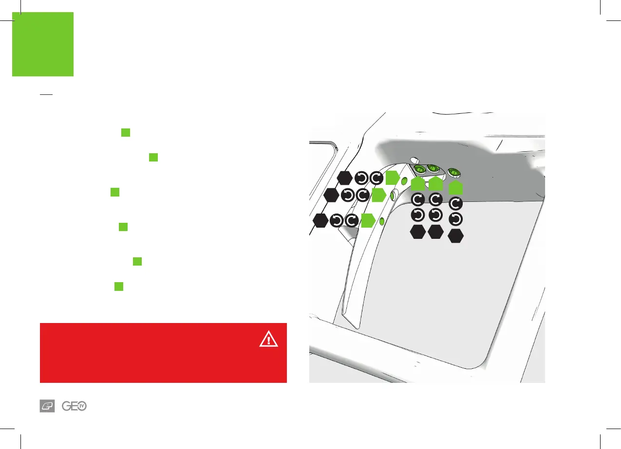
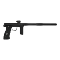
INTRODUCTION
TRIGGER ADJUSTMENT
FIG-1
The spring return screw
A
controls the spring strength of the trigger
return. Clockwise increases the strength, counter-clockwise decreases it.
The trigger shoe retaining screw
B
is only to be removed to change to a
dierent style trigger shoe (sold separately). Remove the frame to access
the screw. Counter-clockwise removes the screw, clockwise tightens it.
The pre-travel screw
C
adjusts the distance the trigger travels before
being pulled. Clockwise reduces the amount of travel (shortening the
trigger), counter-clockwise increases the trigger pull distance.
The microswitch screw
D
adjusts the distance between the trigger
and microswitch. Clockwise reduces the distance, counter-clockwise
increases it.
The magnet adjuster screw
E
adjusts the strength of the trigger return.
Clockwise increases the strength, counter-clockwise reduces it.
The post-travel screw
F
adjusts the distance the trigger travels once
pulled. Clockwise reduces the amount of travel (shortening the trigger),
counter-clockwise increases the trigger pull distance.
WARNING!
Do not wind the screws in too far as this may prevent the marker from ring or
even damage it. If the pre-travel screw is wound in too far this could cause the
marker to re unintentionally.