Planmeca ProOne 9
Installation Manual
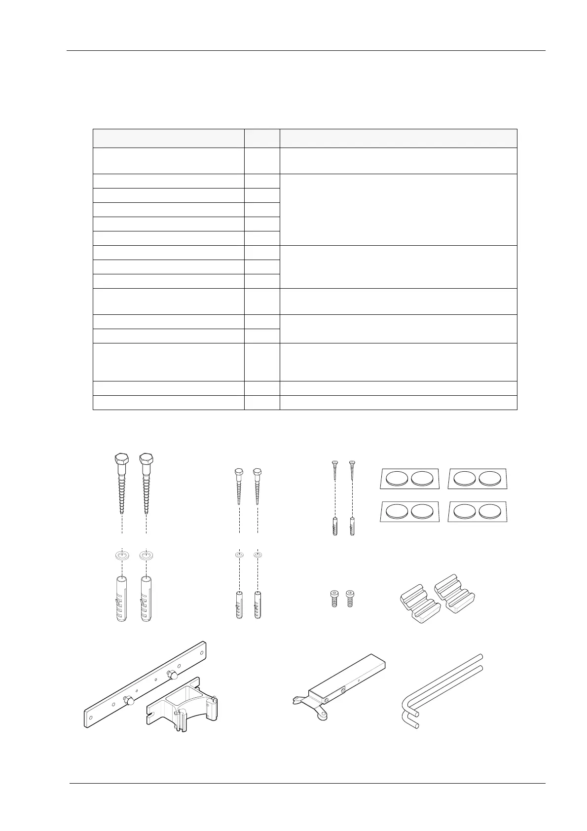
CONTENTS OF THE PACKING
3.2 Mounting accessories
The mounting accessories bag is inside the accessories carton.
The contents are:
PART QTY REFER TO
Felt pads 8 chapter 5 “UNPACKING THE X-RAY UNIT” on page
12
Wall bracket 1 section 6.1 “Attaching the X-ray unit to the wall” on
page 14
Extension plate (optional) 1
Screw M10x70 DIN 571 2
Washer ø10.5/21 DIN 125 2
Plastic insert ø14x70 2
Screw M8x50 DIN 571 2 section 6.2 “Attaching the X-ray unit to the floor” on
page 15
Washer ø8.4/17 DIN 125 2
Plastic insert ø10x50 2
Screw M4x6 DIN 7984 2 chapter 6 “INSTALLING THE X-RAY UNIT” on page
14 (upper arm cover)
Screw 4x30 2 chapter 7 “INSTALLING THE EXPOSURE SWITCH”
on page 18
Plastic insert ø6x30 2
Ferrite beads 2 chapter 7 “INSTALLING THE EXPOSURE SWITCH”
on page 18 and chapter 8 “INSTALLING THE DIG-
ITAL SYSTEM” on page 22
Calibration block 1 Planmeca ProOne X-ray unit Technical manual
Alignment pins 2 Planmeca ProOne X-ray unit Technical manual
Calibration block
ProOne_acc.eps
Alignment pin
Ferrite bead
Screw M4x6 DIN 7984
Plastic insert ø10x50
Plastic insert ø14x70
Washer ø8.4/17 DIN 125
Washer ø10.5/21 DIN 125
Screw M8x50 DIN 571
Screw M10x70 DIN 571
Felt pads ø24
Plastic insert ø6x30
Screw 4x30
Wall bracket
Extension plate
(optional)
Printed copies of this document are considered uncontrolled.
7535.13.Rev001 08.07.2018