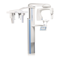
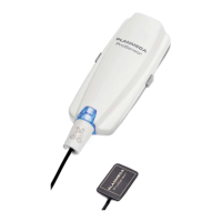
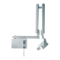
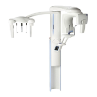
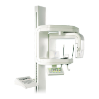
Planmeca ProOne 1
TABLE OF CONTENTS
Installation Manual
1 INTRODUCTION ..............................................................................................1
2 PRE-INSTALLATION INFORMATION .............................................................2
2.1 Radiation protection ....................................................................................................... 2
2.2 Environmental requirements .......................................................................................... 3
2.3 Power requirements ....................................................................................................... 3
2.4 Digital system pre-installation information ..................................................................... 3
2.5 Dimensions for X-ray unit ............................................................................................... 6
2.6 Dimensions for wall bracket and extension plate (optional) ........................................... 7
3 CONTENTS OF THE PACKING ......................................................................8
3.1 Associated documentation ............................................................................................. 8
3.2 Mounting accessories .................................................................................................... 9
4 MAIN PARTS OF THE X-RAY UNIT ..............................................................10
4.1 General view of the system .......................................................................................... 10
4.2 General view of the X-ray unit ...................................................................................... 11
5 UNPACKING THE X-RAY UNIT ....................................................................12
6 INSTALLING THE X-RAY UNIT .....................................................................14
6.1 Attaching the X-ray unit to the wall .............................................................................. 14
6.2 Attaching the X-ray unit to the floor .............................................................................. 15
7 INSTALLING THE EXPOSURE SWITCH ......................................................18
7.1 Movable exposure switch ............................................................................................. 18
7.2 Stationary exposure switch .......................................................................................... 20
8 INSTALLING THE DIGITAL SYSTEM ...........................................................22
8.1 Connecting the Ethernet cable ..................................................................................... 22
8.2 Configuring the Ethernet link ........................................................................................ 23
8.3 Checking the Ethernet link communication .................................................................. 24
8.4 Installing the Dimaxis/Romexis imaging software ........................................................ 25
8.5 Installing the calibration files ........................................................................................ 25
9 CHECKING THE ALIGNMENTS ....................................................................26
9.1 X-ray beam ..................................................................................................................26
9.2 Taking a ball phantom exposure .................................................................................. 26
9.3 Patient positioning lights .............................................................................................. 26
10 DIAGRAMS ....................................................................................................27
Printed copies of this document are considered uncontrolled.
7535.13.Rev001 08.07.2018
 Loading...


