POCLAIN HYDRAULICS
56 REPAR MS25-125 F/GB 800378131M
• Monter l’anneau d’arrêt (077) en
utilisant une pince à anneaux d’arrêt
extérieurs.
• Remove the snap ring (077) us-
ing external snap ring pliers.
• Appliquer l’effort F (voir tableau
page 86
) sur le roulement (074),
puis mesurer le jeu entre la bague
d’appui (076) et l’anneau d’arrêt
(077).
• Déterminer le calage (075) afin
d'obtenir le couple de rotation (C)
correspondant (voir tableau page
86
) (valeur approximative du calage
= mesure + S).
• Apply the F force (see table
page 86
) on the bearing (074), then
measure the clearance between the
thrust ring (076) and the snap ring
(077).
• Determine the shimming (075)
in order to obtain the rotational
torque (C) (see table page 86
)(Ap-
proximate shimming value = meas-
ure + S).
• Relâcher l’effort F. Démonter
l’anneau d’arrêt (077) et la bague
(076).
• Monter le calage (075).
!
LA CALE LA PLUS EPAISSE
DOIT ETRE MONTEE COTE
ROULEMENT
• Remonter la bague (076) (voir
photo 8264).
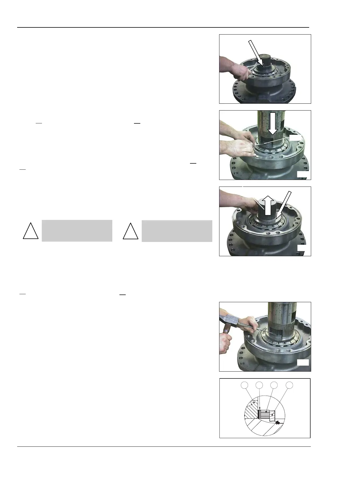
• Monter l’anneau d’arrêt (077)
(voir photo 8265).(l'angle vif opposé
à la bague d'appui (076)) en utilisant
l’effort F initial (voir tableau page
86
)
• Stop the F force. Remove the
snap ring (077) and the thrust ring
(076).
• Install the shimming (075).
!
THE THICKEST SHIM
SHOULD BE MOUNTED TO-
WARDS THE BEARING
• Install the thrust ring (076) (see
picture 8264).
• Install the snap ring (077) (see
picture 8265). (the sharp corner op-
posite to the thrust ring (076) using
the initial F force (see table page
86
).
S’ASSURER :
• De l'impossibilité de tourner la
bague (076) d’appui manuellement.
• Visuellement que le diamètre de
l’anneau d’arrêt (077) n'est pas plus
grand que celui de la bague d’appui
(076).
CHECK :
• that it is not possible to turn the
thrust ring (076) manually
• visually that the snap ring (077)
diameter is not larger then the thrust
ring (076) diameter.
074 075 076 077
2050
8271
8266
075
8270
8265
077