18-92 PN-0908073 Rev. 11
PS 164-2
THE ART OF WELDING
21
2
PS 164-2
A
PS 164-2
1
2
1
3
2
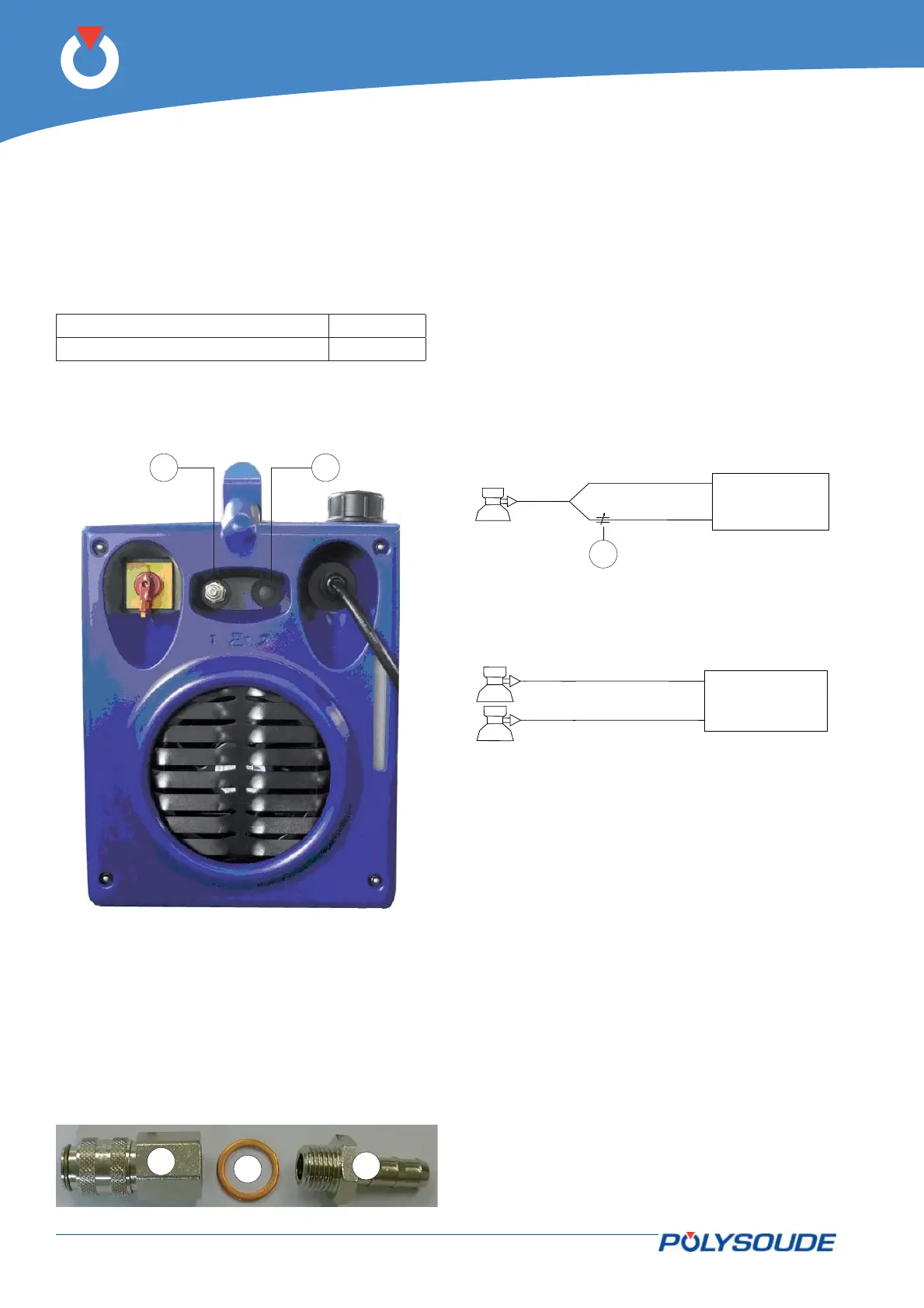
4. 2. 4. Connection with gas supply
Connection with the gas supply is made at the rear-
side of the power source (Fig.4.3) with the appropri-
ate fi ttings. Flow regulators should be used to ad-
just the power source inlet gas stream to the correct
value (see appendix 4 - Spare parts). Before making
any connections, briefl y open the valves to drive out
any impurities.
Fig.4.3, Fig.4.4 & Fig.4.5 - Pos 1 Gas 1
Fig.4.3, Fig.4.4 & Fig.4.5 - Pos 2 Gas 2
To ensure a successful welding cycle, please provide
for a minimum of 2.5 L/min for Argon gas fl ow and
8 L/min for Helium fl ow.
• Gas fi tting female - Part number 01514008 - Item
1.
• Ribbing bush - Part number 00692055 - Item 2.
• Copper seal 13.5x18x1.5. -No part number - Item
3.
Fig. 4.3 - Gas connections at the right side of the
PS 164-2
Gas kit for UHP
This option integrated in the power source enables
to keep a continuous gas fl ow when the UHP head is
not welding.
Gas fl ow is controlled by:
• A valve integrated in the circuit if the gas used is
the welding gas (see Fig.4.4). This valve (Fig.4.4
- Pos A) is adjusted manually.
• The fl owmeter in the gas source (bottle or pipe)
if the gas is different from the welding gas (see
Fig.4.5). The connection is made at the rear side
of the power source (inlet gas 2).
Fig. 4.4 - Diagram to use only one gas
Fig. 4.5 - Diagram to use two different gas
How it works :
If a UHP head is connected, the gas fl ows as soon
as the power source is switched on according to the
fl ow rate pre-set adjusted by means of the valve or
the fl owmeter.
When the welding cycle is started (switch in set up or
weld position), the welding gas fl ows automatically
according to the fl ow controlled by the fl owmeter
until the post gas time has elapsed after welding.
Afterwards the gas keeps on fl owing with continuous
fl ow.
Once the head is disconnected, continuous gas is
stopped.