PN-0908073 Rev. 11 19-92
PS 164-2
THE ART OF WELDING
4. 3. Preparation for work
4. 3. 1. Connection of the remote control pendant
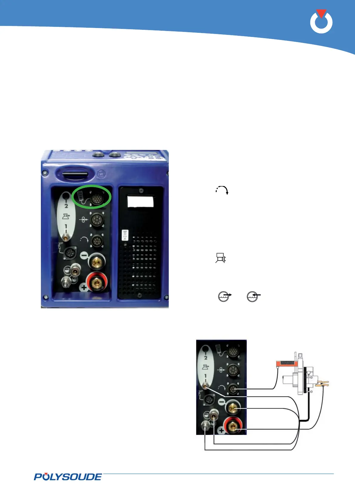
Connection of the remote control pendant is made
with the plug on the right side of the PS 164-2 on
the screw connector.Make sure the securing ring is
tightened properly, otherwise the system may not
function correctly. Warning: the power source will
not work if the remote control pendant is not prop-
erly connected.
Fig. 4.6 - Connection of the remote control pendant
with the PS 164-2
4. 3. 2. Connection of an MU welding head or a TP or TS
tube/tube-plate welding head
◊ Connection of the electrode current cable
Connect the current cable on the "-" terminal with
the quick connector, locking it by a short rotation to
the right.
◊ Connection of the current return cable
Connect the current return conductor cable onto
the "+" terminal marked by a red ring. Connection
is made with a quick connector, by a short rotation
to the right. Connect the other end of the cable to
the workpiece, as close as possible to the joint to be
welded, in an area free from grease and oxide.
◊ Connection of the rotation motor cable
Join the cable on the "Rotation" connector.
(symbol
).
Make sure that the securing ring is properly tight-
ened, otherwise the system may not function cor-
rectly.
◊ Connection of the torch shielding gas hose
Connection is made with a quick push-type self seal-
ing coupling situated at the connection plate of the
power source.
(symbol
).
◊ Connection of the coolant circuit
Connection is made by 2 quick push type self sealing
couplings on the front view.
(symbols
and ).
Fig. 4.7 - Connection of an MU welding head or a
TP/TS welding head