20-92 PN-0908073 Rev. 11
PS 164-2
THE ART OF WELDING
4. 3. 3. Connection of an air cooled closed chamber welding
head
This is the case for type H or UHP Polysoude closed
welding heads.
◊ Connection of the electrode current cable
Connect the current cable on the "-" terminal with
the quick connector, locking it by a short rotation to
the right. This cable is not indicated.
◊ Connection of the current return cable
Connect the current return conductor cable onto the
"+" terminal marked by a red ring. Connection is
made with a quick connector by a short rotation to
the right. This cable is indicated red.
◊ Connection of the rotation motor cable
Connect the cable on the "Rotation" module connec-
tor (symbol
). Make sure that the securing ring
is properly tightened, otherwise the system may not
function correctly
◊ Connection of the torch shielding gas hose
Connection is made with a quickpush type self seal-
ing coupling disconnect fi tting situated at the bottom
left hand corner of the front panel of the PS 164-2
(symbol
1
).
◊ Connection of a bipass plug for the coolant
circuit security for use with air cooled weld-
ing heads.
For UHP before 2003 and H welding heads, it is neces-
sary to introduce the bipass plug to isolate the coo-
ling circuit security in order to avoid a continuously
detected fault.
4. 3. 4. Connection of a liquid cooled closed chamber
welding head
This is the case for type K and MW Polysoude closed
welding heads.
◊ Connection of the electrode current cable
Connect the current cable on the "-" terminal with
the quick connector, locking it by a short rotation to
the right.
◊ Connection of the current return cable
Connect the current return conductor cable to the
"+" terminal with the quick connector, locking it by
a short rotation to the right. This cable is indicated
red.
◊ Connection of the rotation motor cable
Join the cable to the "Rotation" connector (symbol
). Make sure that the securing ring is tight oth-
erwise the system may not function correctly.
◊ Connection of the manual command cable
on the head (MW heads)
Connect the manual commands cable on the FA 5
terminal (Fig. 2.12) on the connection plate.
◊ Connection of the coolant circuit
Connection is made by 2 quick push type self sealing
couplings on the cooling unit RC 200 (symbols
and
).
◊ Connection of the torch shielding gas
Connection is made with a quick disconnect fi tting
situated at the connection panel of the PS 164-2
(symbol
1
).
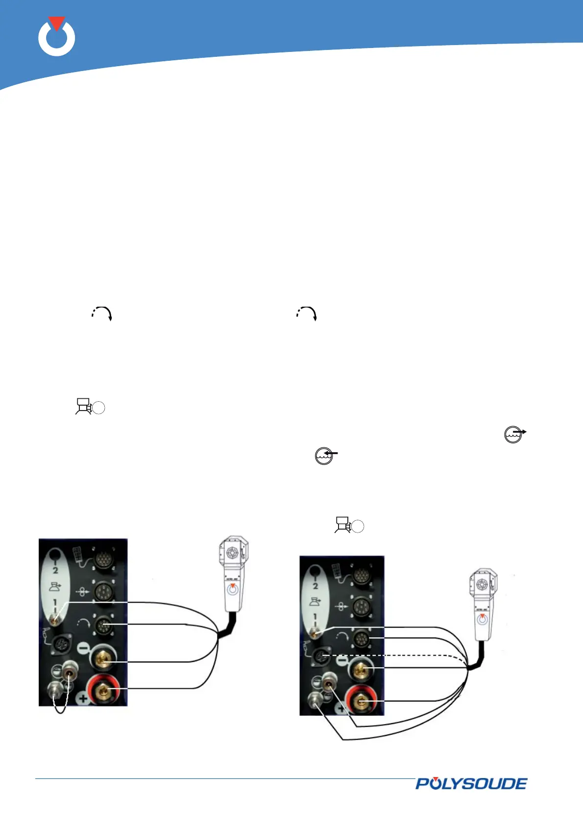
Fig. 4.8 - Connection of an air cooled closed
chamber welding head
Fig. 4.9 - Connection of a liquid cooled closed
chamber welding head ( ---- for heads with
integrated commands)