3-4
3 First Steps
Back view
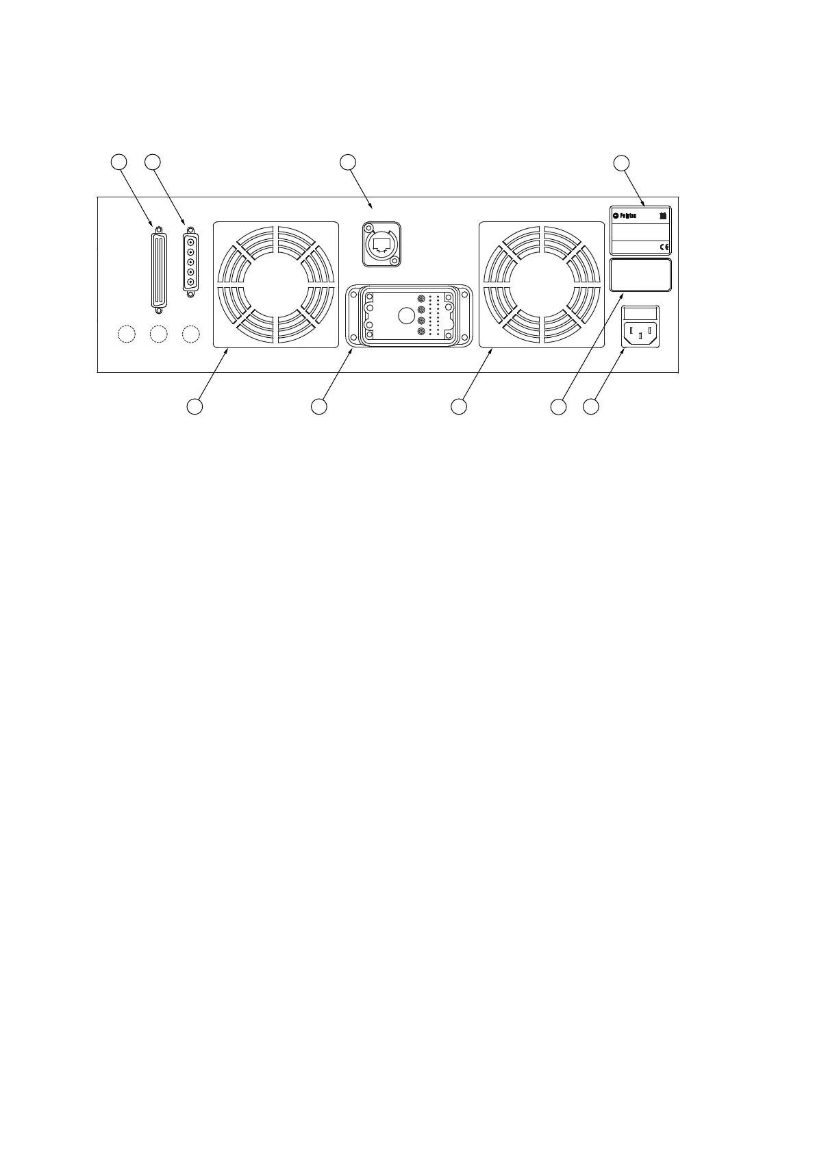
The back view of the front-end is shown in the following figure.
Figure 3.2: Back view of the front-end
1 ACQUISITION 2MHz
connection (SCSI-II type)
Connector for the acquisition cable (Acquisition) to the PC to transmit the
vibrometer, trigger, and reference signals
2 GENERATOR IN
connection (Sub-D jack)
Connection for the generator cable from the PC to transmit the signals of the
function generator
3 CONTROL
network connection (marked in yellow)
Connection for the yellow network cable to the PC for data exchange and to
control the system via the software.
4
Name plate
Plate with information on model, serial number, power specifications, etc.
5POWER
mains connection (socket for standard power cord with built-in fuses)
6
Warning label
7
Cooling fan
8 SCANNING SYSTEM
connection (industrial-style connector)
Connection for the 3D connecting cable (3D Connecting) from the junction box
SCANNING SYSTEM
CONTROL
POWER
VIB
TOP
ACQUISITION 2MHz
GENERATOR IN
VIB
LEFT
RIGHT
VIB
ACHTUNG
!
Vor dem Öffnen
Netzstecker ziehen
WARNING
!
Disconnect Mains
before opening
Manufactured by:
GmbH
D-76337 Waldbronn, Germany
Model No.:
Serial No.:
Mfg.-Date:
x xx xxxx
yyyy
Version:
xx
PSV-500
Mains: 100...240V 50/60Hz
Fuses:
x.x AT
Power cons.: max xxxVA
4
2
1
3
7
875
6