3-5
3 First Steps
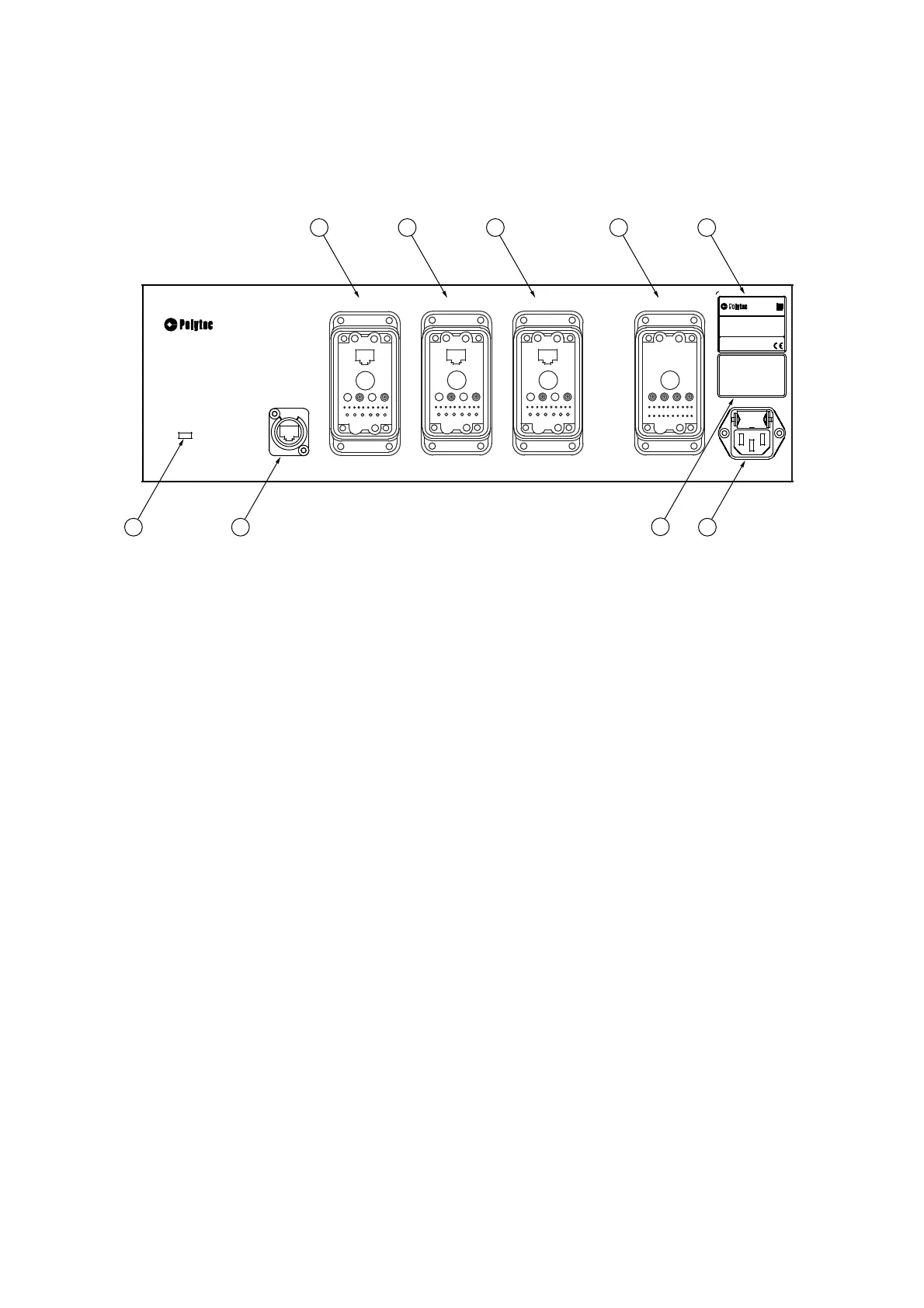
3.2.2 PSV-E-500 Junction Box
Back view
The back view of the junction box is shown in the following figure.
Figure 3.3: Back view of the junction box
1
Connection
TOP/LEFT/RIGHT
(industrial-style connector)
Connections for the main cables (Umbilical) from the TOP, LEFT or RIGHT
scanning heads respectively
2 FRONT-END
connection (industrial-style connector)
Connection for the 3D connecting cable (3D Connecting) to the front-end
3
Name plate
Plate with information on model, serial number, power specifications, etc.
4POWER
mains connection (socket for standard power cord with built-in fuses)
5
Warning label
6VIDEO
network connection (blue background)
Connection for the blue network cable to the PC to transmit the video signal of
the video camera in the TOP scanning head
7POWER
L
ED
L
ED
green: ready to operate
7
1
1
2
4
6
1
3
5
Manufactured by:
GmbH
D-76337 Waldbronn, Germany
Serial No.:
Mfg.-Date:
Version:
x xx xxxx
yyyy
xx
Model :
PSV-E-500
Mains: 100...240V 50/60Hz
Fuses:
x.x AT
Power cons.: max. xxx VA
WARNING !
Disconnect Mains
before opening
ACHTUNG !
Vor dem Öffnen
Netzstecker ziehen
PSV-500
JUNCTION BOX
POWER
VIDEO
LEFT
TOP
RIGHT
FRONT-END
POWER