3-24
3 First Steps
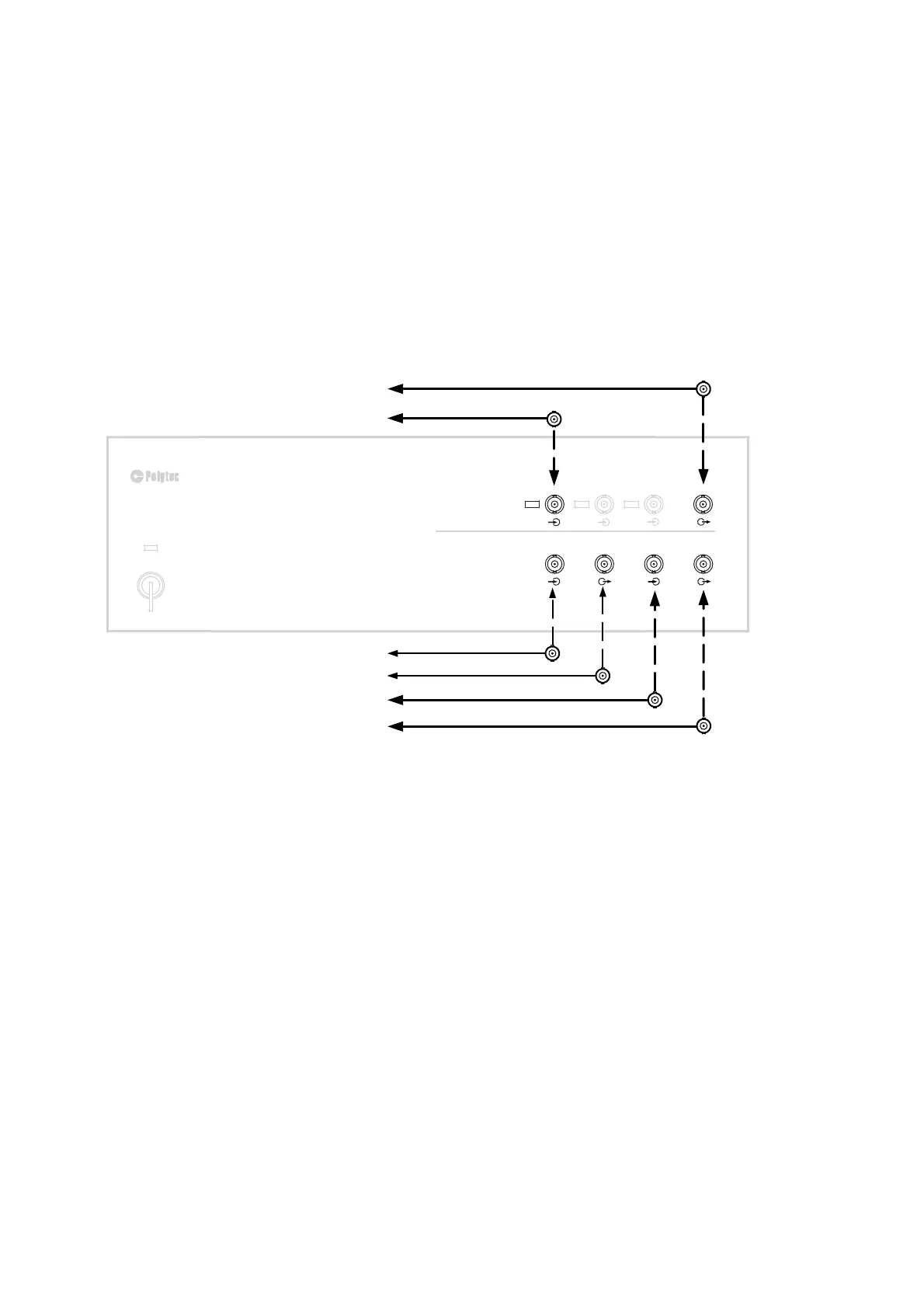
3.4.2 Connecting the Signals
Reference
signal
1. Connect up the reference signal to the
REF 1
BNC jack on the front of the
front-end.
External trigger
2. If required, connect the external trigger signal to the
TRIG IN
BNC jack on
the front of the front-end.
Function
Generator
3. The function generator signal is available at the
SIGNAL
BNC jack on the
front of the front-end.
4. The synchronization pulse of the generator signal is available at the
SYNC
BNC jack on the front of the front-end.
Figure 3.20: Cabling of the front-end
3.4.3 Connecting the Mains Cables
Connect all mains cables of the measurement system to the same earthed
wall outlet to avoid ground loops. Proceed as follows:
1. Connect up all components with the supplied mains cables to the multiple
socket.
2. Connect up the multiple socket with the mains cable to an earthed wall
outlet.
FRONT-END
PSV-F-500
REFERENCE SIGNAL
ACOUSTIC GATE UNIT/
Visual Basic Application
SYNC PULSE
EXTERNAL TRIGGER
GENERATOR SIGNAL
VISUAL BASIC APPLICATION
TRIG IN
AUX OUT
SYNC
AUX IN
SIGNAL
IEPE
IEPE
IEPE
REF2
REF3
REF1
DIGITAL I/O
POWER
ANALOG IN
PSV-500
VIBROMETER FRONT-END
O
I