System Installation
RUBY-9715VG2AR User’s Manual 3-11
3.6 GPIO
The RUBY-9715VG2AR series provides 8 programmable input or output ports that
can be individually configured to perform a simple basic I/O function. Users can
configure each individual port to become an input or output port by programming
register bit of I/O Selection. To invert port value, the setting of Inversion Register
has to be made. Port values can be set to read or write through Data Register.
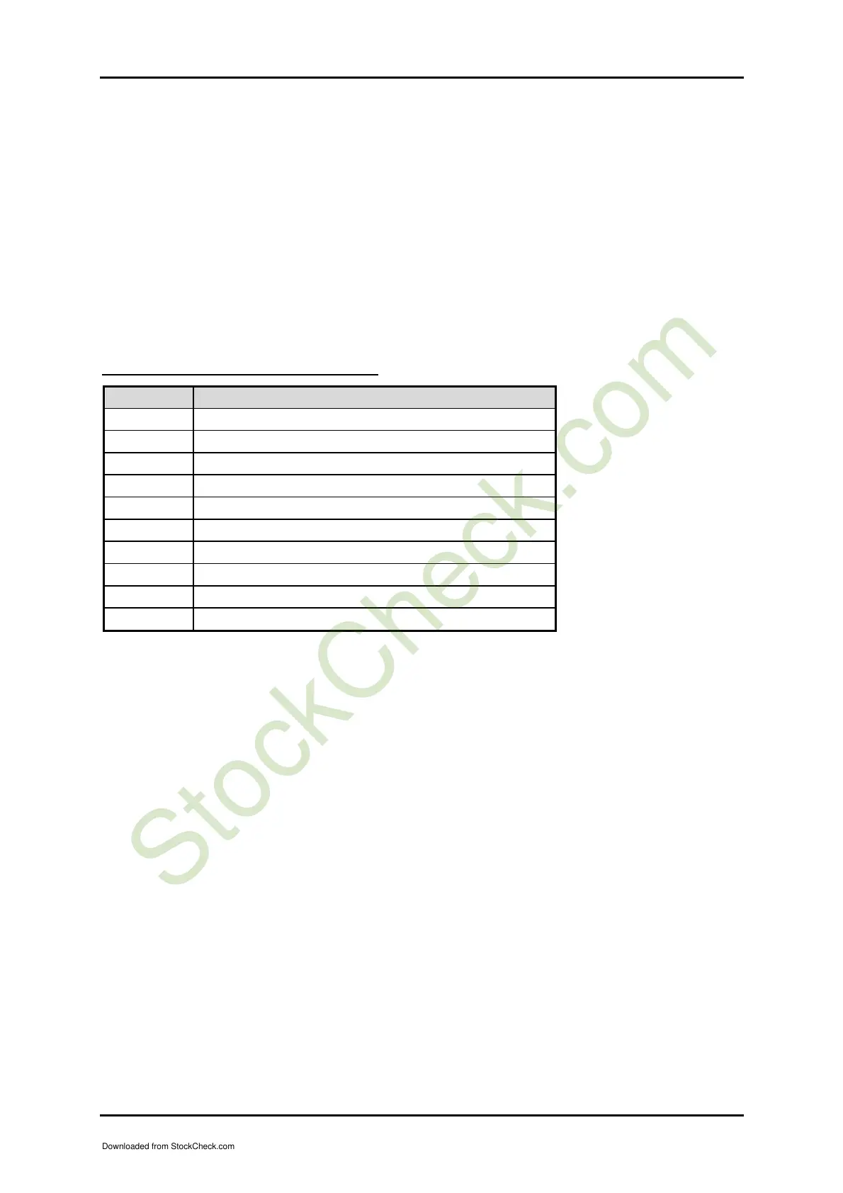
3.6.1 Pin assignment
J38: General Purpose I/O Connector
PIN No. Signal Description
1 General Purpose I/O Port 0 (GPIO0)
2 General Purpose I/O Port 4 (GPIO4)
3 General Purpose I/O Port 1 (GPIO1)
4 General Purpose I/O Port 5 (GPIO5)
5 General Purpose I/O Port 2 (GPIO2)
6 General Purpose I/O Port 6 (GPIO6)
7 General Purpose I/O Port 3 (GPIO3)
8 General Purpose I/O Port 7 (GPIO7)
9 Ground
10 +5V
All General Purpose I/O ports can only apply to standard TTL ± 5% signal level
(0V/5V), and each source sink capacity up to 12mA.
3.6.2 RUBY-9715VG2A GPIO Programming Guide
There are 8 GPIO pins on RUBY-9715VG2A series. These GPIO pins are from SUPER
I/O (W83627THF) GPIO pins, and can be programmed as Input or Output direction.
J38 pin header is for 8 GPIO pins and its pin assignment as following :
J38_Pin1=GPIO1:from SUPER I/O_GPIO10 with Ext. 2.7K PH
J38_Pin3=GPIO2:from SUPER I/O_GPIO11 with Ext. 2.7K PH
J38_Pin5=GPIO3:from SUPER I/O_GPIO12 with Ext. 2.7K PH
J38_Pin7=GPIO4:from SUPER I/O_GPIO13 with Ext. 2.7K PH
J38_Pin2=GPIO5:from SUPER I/O_GPIO14 with Ext. 2.7K PH
J38_Pin4=GPIO6:from SUPER I/O_GPIO15 with Ext. 2.7K PH
J38_Pin6=GPIO7:from SUPER I/O_GPIO16 with Ext. 2.7K PH
J38_Pin8=GPIO8:from SUPER I/O_GPIO17 with Ext. 2.7K PH
<<<<< Be careful Pin9=GND , Pin10=VCC >>>>>
Downloaded from StockCheck.com