DESCRIPTION OF PROGRAMMING PARAMETERS
Parameter /
Default Value
G1.5 / Parameter
initialize
It allows selection of the parameters that we desire to initialize back to the factory
default value.
None of parameters is initialized.
User parameters are only
initialized.
Motor data are only initialized.
All parameters of the drive are
initialized.
G1.6 / To hide
some
configuration
menus
If it is active, then configuration menus will not be accessible. Only visible G1
OPTIONS MENU, G10 LIMITS, and Display groups.
G1.7 / Program
activation
STANDARD
PUMP
MACRO for
VYSTA
programs
It allows selection additional functionalities. If PUMP is selected, then extended
functionality for pumping control G25 will appear as available.
The group G25 will be hidden if the pump program is not active. Furthermore,
there are not available any configuration options related to pump control included
in other parameters.
Once selected the pump program, a character will appear in the upper line of the
display, beside the drive status, indicating constantly that the pump program is
active. The letter “b” in Spanish and the letter “p” for English / German.
The most of parameters relative to the pump control are located in Group 25,
excepting those setting relatives to inputs and outputs that can be found in groups
G4 and G7.
Additionally there are some visualization screens included in visualization groups
SV.5 and SV.8.
For additional information, see the „Pump Application Manual‟ for the SD700.
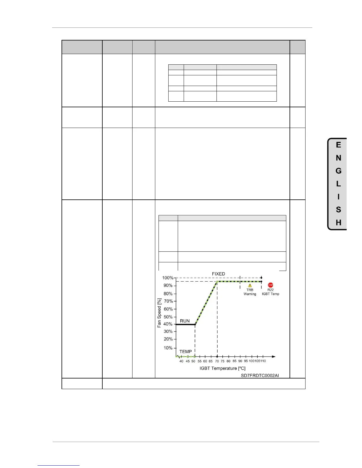
G1.11 / Drive fan
control mode
It allows selecting the operation mode for drive fans. The SD700FR integrates a
VSD system that varies the cooling flow depending on the IGBT temperature.
Start command connect the fans at the minimum speed 40%.
Then fan‟s speed will vary depending on the rectifier‟s IGBT
temperature. The fans will stop 3 minutes after the rectifier
bridge stopping.
Note: Rectifier bridge stops after the sum of the deceleration
ramp time and the Delay IGBT off time.
The fans‟ speed depends on the rectifiers IGBT temperature.
The fans will stop if the temperature is below 51ºC.
Starts the fans at maximum speed when the drive is powered.
Group reserved for the technical service and qualified personnel of Power Electronics