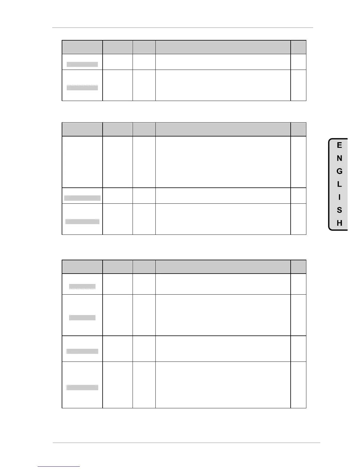
DESCRIPTION OF PROGRAMMING PARAMETERS
Parameter /
Default Value
15 2_Z BAND=OFF
AIN2 ZERO BAND
G4.3.15 / Zero
band filter for
Analogue Input 2
Filtering of analogue input 2 signal. Setting this value we can filter analogue input
2 to avoid possible electrical noise preventing the analogue reading a zero value.
16 FILTER2=OFF
AIN2 STABIL FILT
G4.3.16 / Low
Pass filter for
Analogue Input 2
It allows filtering the Analogue Input 2 signal. Setting the value of this time
constant we can eliminate possible instabilities in the value of the same ones due
to noise, wiring faults, etc.
Note: When applying a Low Pass filter to any analogue signal, a delay time in the
own signal is generated. This delay time is the value of the configured time
constant approximately.
4.4.4. Subgroup 4.4 – S4.4: Pulse Input
Parameter /
Default Value
G4.4.1 / Sensor
units of Pulse
Input
%
l/s
m³/s
l/m
m³/m
l/h
m³/h
m/s
m/m
m/h
Allows selection of the units to measure the flow.
Note: To use this input you should have a flowmeter with a digital pulse output of
pulse width greater than 50ms.
Used for flow limitation algorithm. See S25.10.
2 Pls/s = 100l/s
LIQU AMOUNT/PULS
G4.4.2 /
Flowmeter
configuration
It allows setting the amount of the fluid per pulse received.
For example, if setting is „2Pls/s=100l/s‟, and the present flow is 500l/s, 5
pulses/sec will be received.
3 M Rng=1000l/s
FLOW MAX RANGE
G4.4.3 /
Maximum range
of flow meter
It allows user to set the maximum range of the flow meter. It is used to calculate
the reset level of the flow control algorithm.
Parameter G25.10.4 is linked with the value set in this parameter. Example: If you
set a maximum range of 100 units „G4.4.3=100‟, and the reset level of the flow
algorithm is desired below 30 units, you have to set „G25.10.4=30%‟.
For additional information, see the „Pump Application Manual‟ for the SD700.
4.5. Group 5 – G5: Acceleration and Deceleration Ramps
Parameter /
Default Value
1 ACC1=5.0%/s
INITIAL ACCEL
G5.1 /
Acceleration
ramp 1
Allows user to set acceleration ramp 1. The setting is in acceleration units
(increase in percentage of speed per second). For example, a 10%/s ramp means
that the drive increases its speed by 10% of motor rated speed for each second.
This ramp will be set according to the requirements of each process.
2 DECEL1=3.0%/s
INITIAL DECEL
G5.2 /
Deceleration
ramp 1
Allows user to set deceleration ramp 1. The setting is in deceleration units
(decrease in percentage of speed per second). For example, a 10%/s ramp
means that the drive decreases its speed by 10% of motor rated speed for each
second. This ramp will be set according to the requirements of each process.
Note: For drives which input voltage is 400V, the default values will be:
- From 6A to 48A =10%/sec
- From 60A to 170A =5%/sec
- From 210A to Imax =2%/sec
3 ACC2=1.0%/s
SECOND ACCELE
G5.3 /
Acceleration
ramp 2
Allows user to set the alternative acceleration ramp. The setting is based in
acceleration units (increase in percentage of speed per second), like the main
ramp setting. The drive will apply acceleration ramp 1 until motor speed exceeds
the value set in 'G5.5 BRK ACC'. From here on it will apply the alternative ramp
value. If 'G5.5 BRK ACC = OFF' no ramp change will occur.
4 DECEL2=1.0%/s
SECOND DECELE
G5.4 /
Deceleration
ramp 2
Allows user to set the alternative deceleration ramp. The setting is in deceleration
units (decrease in percentage of speed per second), like the main ramp setting.
The drive will apply deceleration ramp 2 until motor speed is below the value set
in 'G5.6 BRK DEC'. From here on it will apply the alternative ramp value. If 'G5.6
BRK DEC = OFF' no ramp change will occur.
Note: For drives which input voltage is 400V, the default values will be:
- From 6A to 48A =10%/sec
- From 60A to 170A =5%/sec
- From 210A to Imax =2%/sec