DESCRIPTION OF PROGRAMMING PARAMETERS
4.20. Group 20 – G20: Communication Buses
4.20.1. Subgroup 20.0 – S20.0: Communications Control
Parameter /
Default Value
G20.0.1 /
Communications
Control
Selection of the communication bus through which the equipment is controlled
Note: This parameter is only functional after the boot up.
4.20.2. Subgroup 20.1 – S20.1: Modbus RTU
Parameter /
Default Value
1 COMMS T/O =OFF
COMMS TIMEOUT
G20.1.1 /
Communication
timeout
MODBUS RTU
If this time has elapsed from the last valid data transmission a communication
timeout trip can be generated if the user requires it.
Serial communication with the drive is possible through RS232 terminals, RS485
terminals, or through optional serial communication interfaces.
Note: Do not modify this parameter if is not necessary.
2 COMM ADDR =10
COMM ADDRESS
G20.1.2 /
Communication
address
Sets the identification address assigned to the drive for communication via the
Modbus network. If communication is required with several drives a different
address is required for each unit.
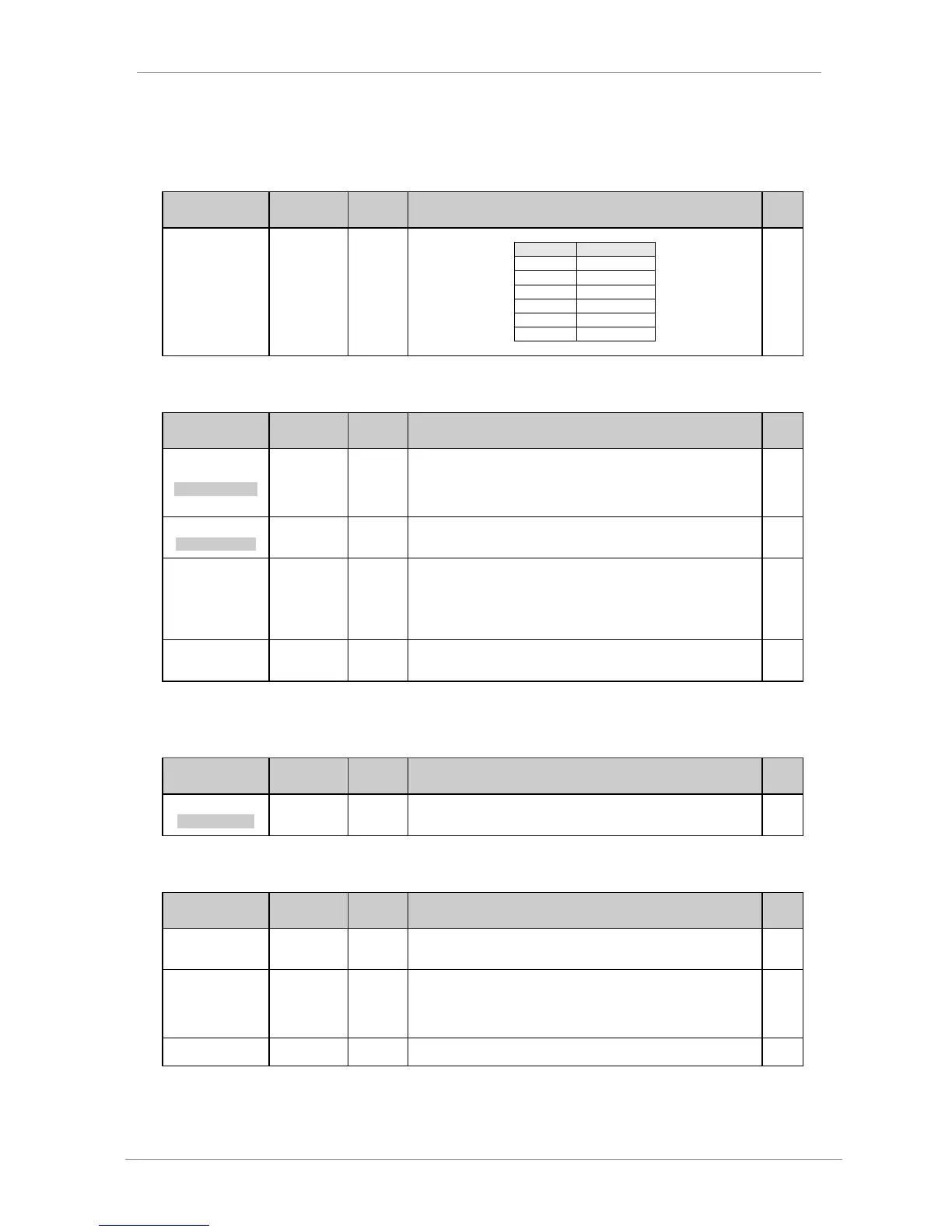
G20.1.3 /
Communication
speed
600
1200
2400
4800
9600
19200
Sets the data transmission speed for MODBUS serial communications. This rating
should be the same as the rating of the master of the communication bus on
which the drive is integrated.
G20.1.4 /
Communication
parity
MODBUS parity setting. Used for data validation. If you do not want to validate
data, set this parameter to „NONE‟. Parity selection should be the same as the
parity of the master of the communication bus on which the drive is integrated.
4.20.3. Subgroup 20.2 – S20.2: PROFIBUS
Parameter /
Default Value
1 NODE ADDR=10
NODE ADDRESS
G20.2.1 / Slave
address in
Profibus network
Sets the identification address assigned to the drive for communication via
Profibus network. If communication is required with several drives a different
address is required for each unit.
4.20.4. Subgroup 20.3 – S20.3: CANOPEN
Parameter /
Default Value
G20.3.1 /
Canopen slave
address
The Node slave address is assigned
G20.3.2 / Bus
speed connected
to drive
1mbps
10mbps
125mbps
250mbps
500mbps
Set the bus speed at which the drive will be connected.
Display screen through which the speed referenced can be seen through the
Canopen