COMMONLY USED CONFIGURATIONS
G4: Inputs – S4.1: Digital Inputs.
G4.1.1 / Main Control Mode
2 REMOTE (Drive control is done through control terminals).
G4.1.4 / Digital Inputs configuration
selection
1 ALL PROGRAMMABLE (all digital inputs can be individually
configured by the user).
G4.1.5 / Multi-function Digital Input 1
configuration
05 Start/Stop (Allows the start/stop command to be given by a
switch).
G4.1.6 / Multi-function Digital Input 2
configuration
15 Reference 2 (It allows selecting the alternative speed
reference programmed in G3.2.)
Set the DC bus voltage in accordance with the installation.
Set the displacement power factor (cos PHI) as 1.
G22.3 / CosPHI characteristics
Set the cos PHI as capacitive.
Set the rectifier bridge IGBT switching frequency to 2800Hz.
Set the delay of the rectifier bridge switching off to 0.
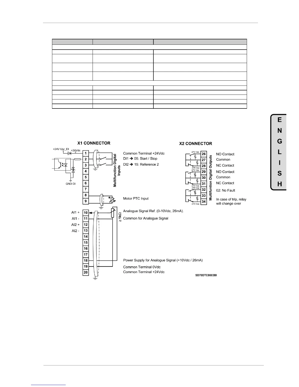
7.2.2. Connections drawing
Terminals 1 and 2: start / stop command (NO status).
Terminals 1 and 3: alternative reference command (NO status).
Figure 7.1 Start / Stop commands by terminals and speed reference by analogue input
Note: Use screened cables for the controls and connect screen to ground.