DESCRIPTION OF PROGRAMMING PARAMETERS
4.14. Group 14 – G14: Multi-references
Parameter /
Default Value
1 MREF 1=+10.0%
MULTI-REFERENCE1
G14.1 / Multi-
reference 1
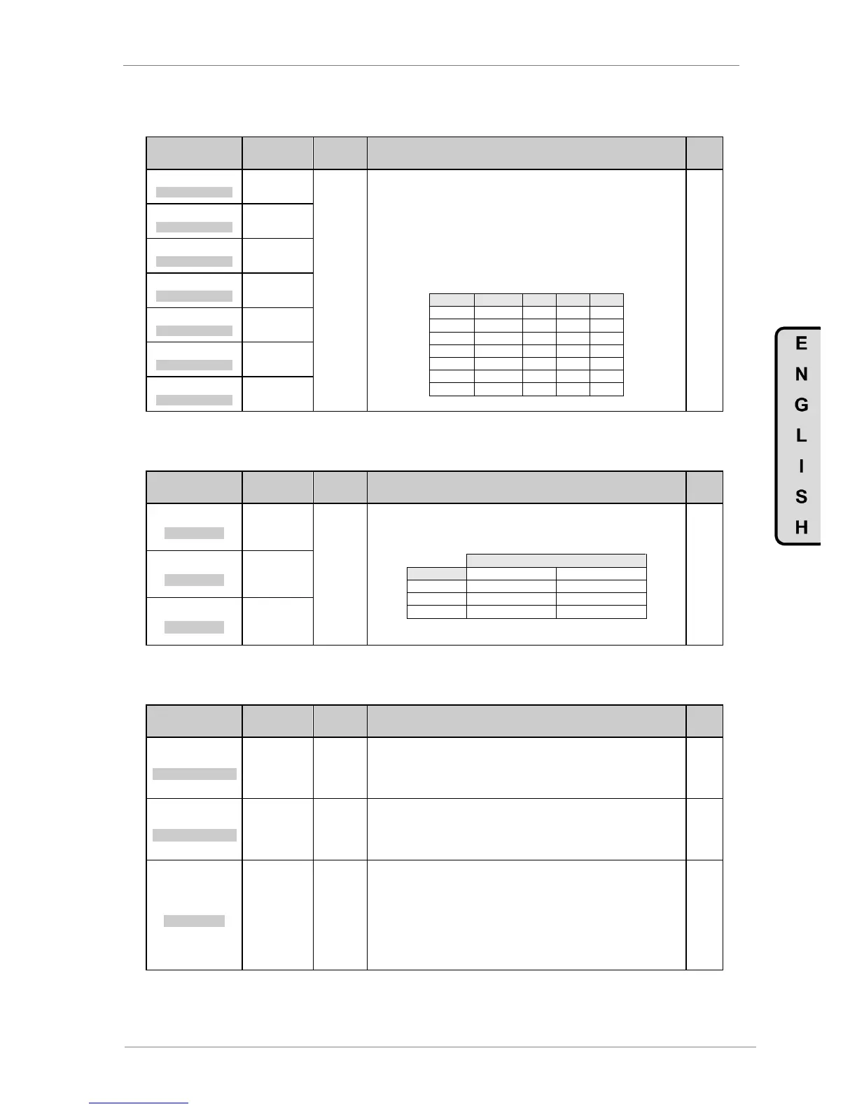
It allows setting of multiple references. These references will be activated using
digital inputs configured as multiple speed references or PID references.
To use this function select operating mode, „G4.1.4 DIGIT I MODE=2 or 3' (2 or 3-
wires multi-reference). It is necessary to select the multi-references as the speed
reference in parameter „G3.1 REF 1 SPD=MREF‟ or as a PID references in „G6.1
SEL REF=MREF‟.
Units are set in either percentage of motor rated speed or feedback analogue
input range (if an analogue unit is selected).
The following table shows the relationship between DI4,DI5, DI6 inputs when
activated in multi-reference mode (as a percentage of motor rated speed):
Note: 0: Not active and X: Active.
2 MREF 2=+20.0%
MULTI-REFERENCE2
G14.2 / Multi-
reference 2
3 MREF 3=+30.0%
MULTI-REFERENCE3
G14.3 / Multi-
reference 3
4 MREF 4=+40.0%
MULTI-REFERENCE4
G14.4 / Multi-
reference 4
5 MREF 5=+50.0%
MULTI-REFERENCE5
G14.5 / Multi-
reference 5
6 MREF 6=+60.0%
MULTI-REFERENCE6
G14.6 / Multi-
reference 6
7 MREF 7=+70.0%
MULTI-REFERENCE7
G14.7 / Multi-
reference 7
4.15. Group 15 – G15: Inch Speeds
Parameter /
Default Value
1 INCH1=+0.00%
INCH SPEED 1
Allows setting of the value of the three possible motor inch speeds. Inch speed
selection is possible through a comparator output (directly) or by a digital input
combination. If digital inputs are used for this purpose they should be configured
as 'START + INCH1' or 'START + INCH2'. See G4.1.5 to G4.1.10.
Note: The activation of this function includes the start command. Therefore this
signal has priority over any other input configured as „Start‟.
2 INCH2=+0.00%
INCH SPEED 2
3 INCH3=+0.00%
INCH SPEED 3
4.16. Group 16 – G16: Skip Frequencies
Parameter /
Default Value
1 SKIP 1=+0.0%
SKIP FREQUENCY 1
Allows user to select the first skip frequency to avoid resonance frequencies or
frequencies where it is not desirable for the motor to operate. Drive passes
through this frequency value during acceleration and/or deceleration but will not
remain operating at this frequency. Once this value is set, the bandwidth (G16.3)
will be based on it, forming a frequency range that the drive will avoid.
2 SKIP 2=+0.0%
SKIP FREQUENCY 2
Allows user to select the second skip frequency to avoid resonance frequencies or
frequencies where it is not desirable for the motor to operate. Drive passes
through this frequency value during acceleration and/or deceleration but will not
remain operating at this frequency. Once this value is set, the bandwidth (G16.3)
will be based on it, forming a frequency range that the drive will avoid.
3 SKIP BAND=OFF
OFFSET BAND
Sets the skip frequency bandwidth.
For example, if 10% is set, the avoided frequencies will be from freq (G16.1) – 5%
to freq (G16.1) + 5% and from freq (G16.2) – 5% to freq (G16.2) + 5%. Supposing
that the selected range goes from 20% to 30%. In case of the frequency is within
that band, for example 27%, there is two situations:
a) Drive is accelerating: so the frequency will be increased up to 27%,
but it will not remain here, it will be increased up to 30%.
b) Drive is decelerating: so the frequency will be decreased down to
27%, but it will not remain here, it will be decreased down to 20%.