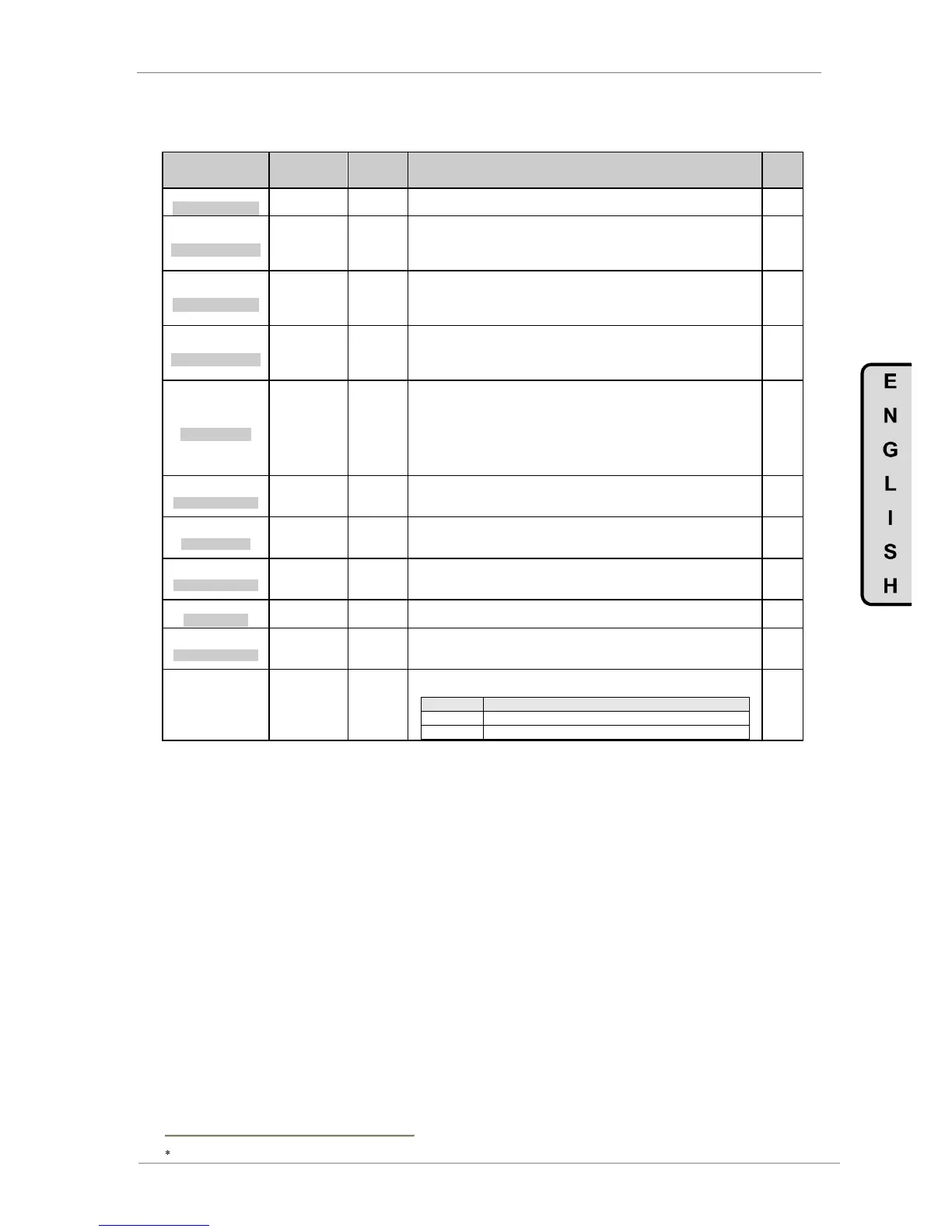
DESCRIPTION OF PROGRAMMING PARAMETERS
4.10. Group 10 – G10: Limits
Parameter /
Default Value
1 MIN1 SP=+0.00%
SPEED MIN LIMIT1
G10.1 / Minimum
speed limit 1
This sets the minimum speed limit 1 that can be applied to the motor by the drive.
It is set in percentage of motor rated speed.
2 MAX1 SP=+100%
SPEED MAX LIMIT1
G10.2 /
Maximum speed
limit 1
This sets the maximum speed limit 1 that can be applied to the motor by the drive.
If the reference is higher than the value set in this parameter, the drive will ignore
that reference and will operate the motor at the value set in this screen.
It is set in percentage of motor rated speed.
3 MIN2 SP=-100%
SPEED MIN LIMIT2
G10.3 / Minimum
speed limit 2
This sets the minimum speed limit 2 that can be applied to the motor by the drive.
It is set in percentage of motor rated speed.
Note: Selection of minimum speed limit 2 is done via a digital input or comparator
output function.
4 MAX2 SP=+100%
SPEED MAX LIMIT2
G10.4 /
Maximum speed
limit 2
This sets the maximum speed limit 2 that can be applied to the motor by the drive.
If the reference is higher than the value set in this parameter, the drive will ignore
that reference and will operate the motor at the value set in this screen.
It is set in percentage of motor rated speed.
5 I LIMIT=___A (*)
MAX CURRENT
Output current limit. Motor current will be within this programmed limit. When this
protection is active the SD700FR status of current limitation (ILT) is displayed.
Note: We do not recommend that current limit works constantly in applications
when the motor is at steady speed status. Damage may occur to the motor and
torque variations can affect the load. Current limit should work only when an
overload occurs, or due to excessive acceleration and deceleration values, or
because motor data details are entered incorrectly.
6 I LIM TO= OFF
TIMOUT MAX CURRE
G10.6 / Trip time
because of
current limit
If the drive is operated continually at current limit for the time set in this screen the
drive generates a fault.
7 I. MAX2=____A (*)
MAX CURRENT 2
G10.7 /
Alternative
current limit
This limit operates with the same philosophy than G10.5, but for the second
current limit.
8 MI2 brSP=OFF
MAX CURR BRK SPD
G10.8 / Change
speed for Imax 2
It allows setting the speed level to change from current limit 1 to current limit 2.
Additionally it is possible to select the alternative current limit 2 using a digital
input configured as option 23.
9 MAX TOR=+150%
MAX TORQUE
This value is the maximum motor torque the drive will allow the motor to supply to
the load. It is set in percentage of motor rated torque.
10 T LIM TO=OFF
TIMEOUT MAX TORQ
G10.10 / Trip
time because of
torque limit
If the drive is operated continually at torque limit for the time set in this screen the
drive generates a fault.
G10.11 / To
enable speed
inversion
The drive can be configured to prevent the motor running in negative direction.
Motor running in negative rotation direction is not allowed.
Motor running in both rotation directions is allowed.
This value depends on the drive rating.