DESCRIPTION OF PROGRAMMING PARAMETERS
4.4. Group 4 – G4: Inputs
4.4.1. Subgroup 4.1 – S4.1: Digital Inputs
Parameter /
Default Value
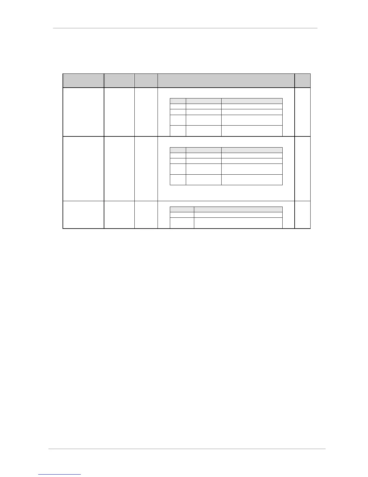
G4.1.1 / Main
Control Mode
It allows user to set the control mode for the drive commands (Start/Stop, Reset,
...).
Control mode 1 is not operative.
Drive control is done by keypad.
Drive controlled through control
terminals.
Drive controlled through
communication bus.
G4.1.2 /
Alternative
Control Mode
It allows user to set the secondary control mode for the drive commands
(Start/Stop, Reset, ...).
Control mode 2 is not operative.
Drive control is done by keypad.
Drive controlled through control
terminals.
Drive controlled through
communication bus.
Note: Control mode 2 will be activated through digital inputs exclusively. To use
this set one of the digital inputs to '17 CONTROL 2'. When this input is
activated, auxiliary control mode will be activated.
G4.1.3 / Reset
from keypad
It allows user to reset faults from the keypad unit (LOCAL).
It is not possible to reset from the keypad unit.
The drive can be reset via the reset button on the
keypad unit.