DESCRIPTION OF PROGRAMMING PARAMETERS
Parameter /
Default Value
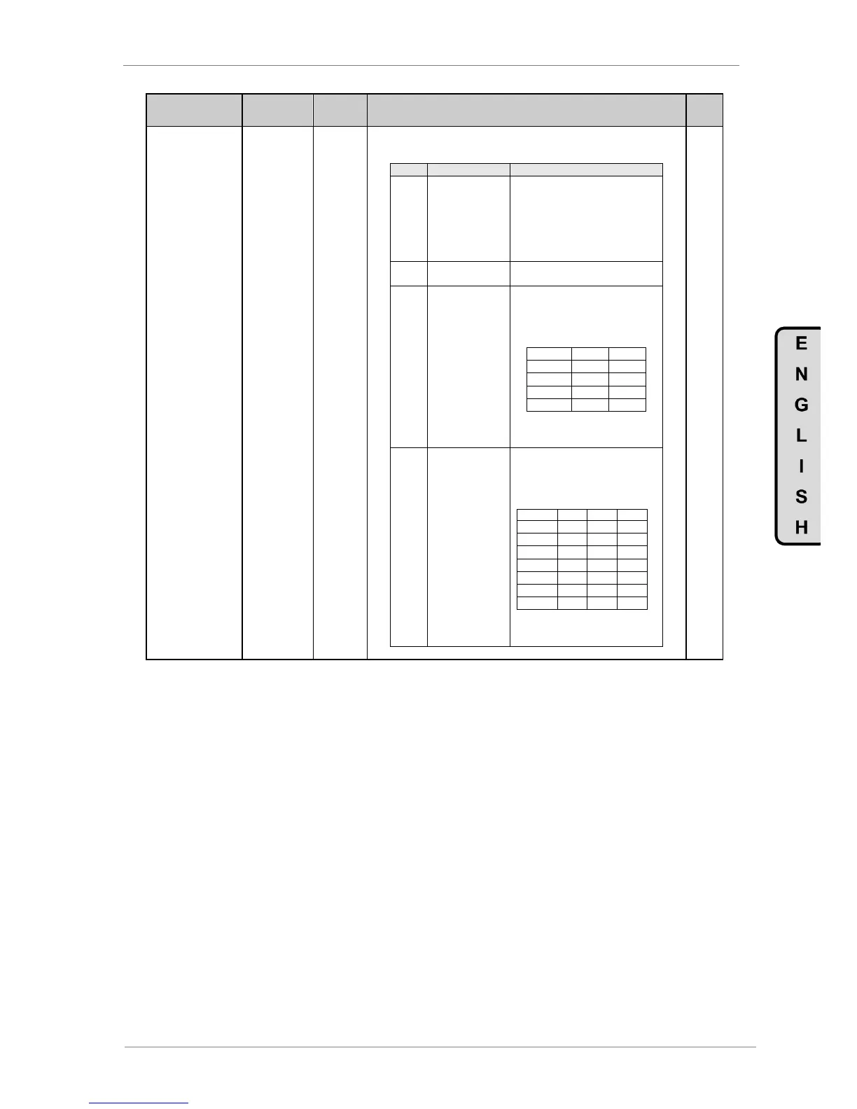
G4.1.4 /
Selection of
Digital Inputs
configuration
It allows user to configure the digital inputs for different functions. All the options
described below will program to all the digital inputs simultaneously, except for
option '1 All Programmable', which allows to configure their in a separate way.
'Start/Stop and Reset' by terminals.
DI1 = 01 Start (NO)
DI2 = 04 Stop 1-Reset (NC)
DI3 = 03 Stop 2-Reset (NC)
DI4 = 15 Reference 2 (NO)
DI5 = 10 Speed Inversion (NO)
DI6 = 17 Control 2 (NO)
Inputs configuration individually by
user. See G4.1.5 to G4.1.10.
Digital inputs 5 and 6 are
programmed as multiple references
(of speed or PID references) for up
to 4 preset speeds. The remaining
inputs are user programmable.
Note: It is necessary to set G3.1
REF1 SPD=MREF or G3.2 REF2
SPD=MREF.
Digital inputs 4, 5 and 6 are
programmed as multiple references
(of speed or PID references) for up
to 7 preset speeds. The remaining
inputs are user programmable.
Note: It is necessary to set G3.1
REF1 SPD=MREF or G3.2 REF2
SPD=MREF.
Note: See following page.