COMMONLY USED CONFIGURATIONS
7. COMMONLY USED CONFIGURATIONS
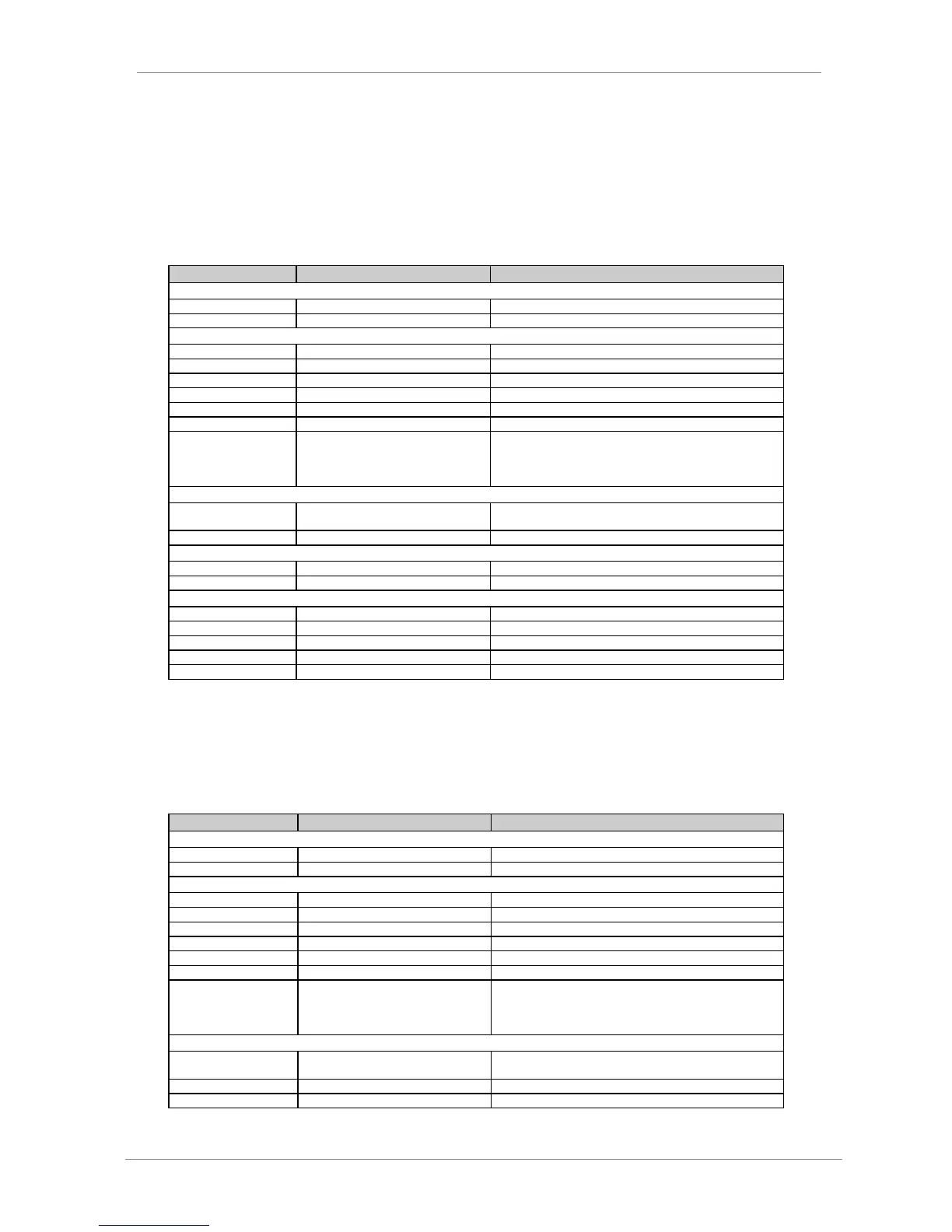
7.1. Start / Stop Commands and Speed Reference by Keypad
7.1.1. Parameters Configuration
G1.4 / Language selection
G1.7 / Program activation
G2.1 / Motor rated current
__A (Set according to motor nameplate).
G2.2 / Motor rated voltage
__V (Set according to motor nameplate).
__kW (Set according to motor nameplate).
__rpm (Set according to motor nameplate).
__ (Set according to motor nameplate).
__Hz (Set according to motor nameplate).
G2.7 / Motor cooling at zero speed
Use the following values as a reference:
Submersible pumps and non-deflagrating motors 5%
Self-cool motor 63%
Force-cooled motor 100%
G3.1 / Speed reference source 1
LOCAL Reference will be determined by keypad and is set in
G3.3 'Local Speed Reference'.
G3.3 / Local Speed Reference
G4: Inputs – S4.1: Digital Inputs.
G4.1.1 / Main Control Mode
1 LOCAL (Drive control is done by keypad).
Y YES (Enables reset by keypad).
Set the DC bus voltage in accordance with the installation.
Set the displacement power factor (cos PHI) as 1.
G22.3 / CosPHI characteristics
Set the cos PHI as capacitive.
Set the rectifier bridge IGBT switching frequency to 2800Hz.
Set the delay of the rectifier bridge switching off to 0.
7.2. Start / Stop Commands by Terminals and Speed
Reference by Analogue Input
7.2.1. Parameters Configuration
G1.4 / Language selection
G1.7 / Program activation
G2.1 / Motor rated current
__A (Set according to motor nameplate).
G2.2 / Motor rated voltage
__V (Set according to motor nameplate).
__kW (Set according to motor nameplate).
__rpm (Set according to motor nameplate).
__ (Set according to motor nameplate).
__Hz (Set according to motor nameplate).
G2.7 / Motor cooling at zero speed
Use the following values as a reference:
Submersible pumps and non-deflagrating motors 5%
Self-cool motor 63%
Force-cooled motor 100%
G3.1 / Speed reference source 1
LOCAL Reference will be introduced by keypad and is set in
G3.3 'Local Speed Reference'.
G3.2 / Speed reference source 2
AI1 Reference will be introduced by Analogue Input 1.
G3.3 / Local Speed Reference