FAULT MESSAGES. DESCRIPTIONS AND ACTIONS
6.1.4. List and Solutions of Rectifier bridge faults
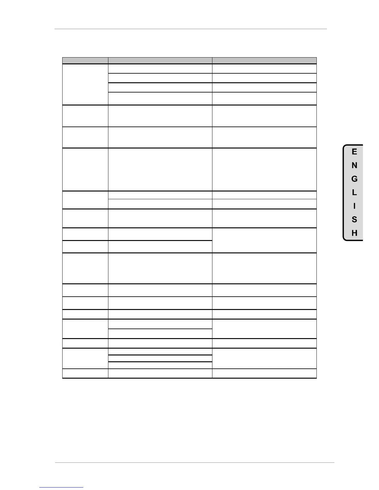
The input current measure signal has been lost.
Check the current sensors are correctly fastened.
The input voltage measure signal has been lost.
Check the voltage sensors are correctly fastened.
Incorrect setting of the current control loop.
Readjust the parameters G22.10.5 and G22.10.6.
A voltage dip has occurred.
Try to reset the fault. If the fault persists contact
Power Electronics for technical service.
Deceleration ramp too high (parameters „G5.2
DECEL1‟ and „G5.4 DECEL2‟) or rectifier‟s “PID
Vdc” parameters are too slow.
Decrease deceleration ramps. If the fault persists
contact Power Electronics for technical service.
Softcharge contactor or resistors failure.
Try to reset the fault. Disconnect and re-connect
again the input power. If the fault persists contact
Power Electronics for technical service.
R4 OVERLOAD R+
R5 OVERLOAD R-
R6 OVERLOAD S+
R7 OVERLOAD S-
R8 OVERLOAD T+
R9 OVERLOAD T-
R10 MULTI O.L.
Rectifier bridge IGBTs desaturation. See possible
causes for faults F4-F9.
Check if there is possible input wiring faults. If the
fault persists after disconnecting input wires
request technical assistance.
Check the input wiring is correctly installed.
Input voltage measure has been lost.
Check the voltage sensors are correctly fastened.
Possible internal wiring disconnection. Check the
input wiring is correctly installed and the status of
the input power supply is correct.
Voltage lost in the capacitor of the LCL filter.
Possible internal wiring disconnection. Disconnect
and re-connect again the input power. If the fault
persists contact Power Electronics for technical
service.
DC bus voltage signal is lost.
Feedback signal from the softcharge contactor is
lost.
Feedback is wrong wired.
Check that voltage signal connector is correctly
fastened. If the fault persists contact Power
Electronics for technical service.
When the fault is produced when the VFD is power
supplied, stop, check the contactor and start.
The fans of the LCL filter zone are faulty.
Check that the fans rotate smoothly and there isn‟t
any obstacle.
Low bus voltage detected.
Input voltage is lost and the electronics power
supply keep powered
Fiber optic cable is interrupted.
Check fiber optic cable about visual damages.
Check the parameter “G22.11.7 I Imb” value. If the
fault persists contact Power Electronics technical
service.
Check power wiring about visual damages.
Check the parameter “G22.11.5 I lim REC” value
and the load.
See possible causes for F34 fault.
See possible solutions described for F34 fault.