C8
Rev.304
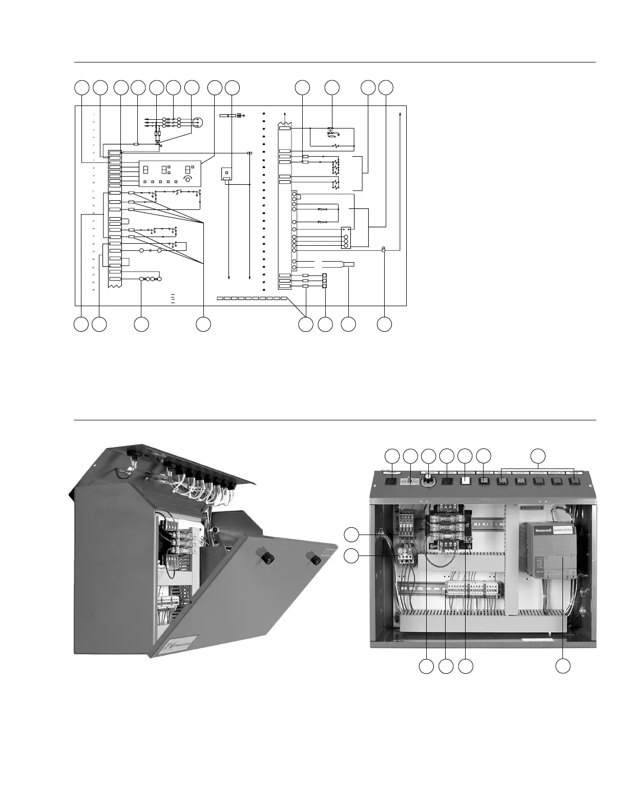
This Total Access Control Panel is typical in general
construction and configuration for the fuel and mode of
operation indicated. Each burner is shipped with a wiring
diagram, as well as specific documentation on specific
panel components. Side view of removable front and top
Figure 6B
Alpha System™ Circuit Board Typical Electrical Schematic with Light & Switch Circuit Board
1. Control Switch
2. Fuel Changeover Switch
3. Manual Potentiometer
4. Manual-Auto Select
Switch
5. Power On Indicator
6. Main Fuel Indicator
7. Auxiliary Functions
8. Motor Starter
9. Motor Overloads
10. Stepdown Control Voltage
Transformer
11. DIN Rail Mounted Terminal
Strips
12. Primary & Secondary Fuses
1. Main Circuit Board
2. (L1 Main) Hot 115 Volt Power
Connection*
3. (L2) Neutral 115 Volt Wiring
Connection*
4. Control Circuit Fuse
5. Primary Fuses
6. Motor Starter
7. Step-Down Transformer
8. Light & Switch Circuit Board
9. Auxiliary Light Board Connection
(Typical)
10. Wiring Terminal Strip Identification
11. Gas Ignition Transformer
12. Operating Valve Connections
13. Modulation Motor Connections
14. Limit Device Connections (Typical)
15. Running Interlock Connections
16. Motor Starter Coil
17. Operating Control Connection
18. Flame Detector Connection
19. Alarm Buzzer or Bell
panel doors. To remove front panel door, place unlatched
door in closed position and lift it up. For total access to
components mounted in the top panel, remove the four
holding screws and rotate the top panel upward, around
the hinge located at the top rear of the panel box.
Figure 6C
Total Access Control Panel (Patented) For Combination Gas/Oil Modulation Burners
8
9
13
12
11
10
1
3
4
2 7
5 6
* L1 Main 115 volt hot incoming power terminal is located at
the top of the circuit board. L2 Neutral 115 volt power terminal
is located on the lower set of terminals at the bottom of the
main circuit board. The L1 Fused terminal (not shown) located
on the lower set of terminals is for factory use and should not
be used for incoming power connections.
10 171615
14 10 18 19
L2
L1 MAIN
P2
CS
_
Y
CS
_
B
WHT
RED
BLU
CL1
X-ALARM
CL2
OL1
OL2
GL1
GL2
A1
A2
O11
O12
L2
BM
96 95 A1A2
NO NO
1MS
1MS
3PS
BURNER MOTOR
STARTER
2,19
COMB.
AIR SW.
PRESS. SW.
HIGH GAS
1PS
2PS
LOW GAS
PRESS. SW.
GL1
GL2
CL2
XA
CL1
E5
E4
E3
E2
E1
1CBL / WHT P1
OFF
POWER
ON
ON
DEMAND
MAIN
FUEL
FSG
ALARM
GAS
ON
OFF
FUEL SELECT MODULATION
MANUAL
AUTO
MAX
MIN
LOW
WATER
1MB
Q7800C1027
FUSE & HOLDER
2FU
STEPDOWN TRANSFORMER
PRIMARY FUSES1FU
1T
L1
L2
L3
T1
T2
T3
1MS
1M
BURNER
MOTOR
LISTED GROUNDING BAR AND/OR
GREEN SCREW MOUNTED IN PANEL
AND WIRED TO EARTH GROUND
LABELED EQUIPMENT GROUND
1ALB
AUX. LIGHT
BOARD
LIGHT & SW.
CIRCUIT BOARD
L2 4
IGNITION
ON
OPERATING
CONTROL
10C
1HL
HIGH
LIMIT
CUTOFF
LOW WATER
1LLS
2 GV1 CL1
CL2 XA
GL1 GL2 R1 W1
B1
A
B
W
R
BB1
R1
W1
W
R
B
1MMC
MODULATING
CONTROLLER
BLUE
(UV SCAN ONLY)
WHITE
1FD
SCANNER
1AB
G
F
ALARM BELL
B
R
W
1MM
WH BK
3
14
13
12
L2
19
2LS
MODULATING
MOTOR
PURGE INTERLOCK
(IN MOD. MOTOR)
LOW FIRE START
INTERLOCK
IN MOD. MOTOR
1LS
RY
18
5
20
4
1FSG
RM7800L OR RM7840L
6VLV
5VLV
4VLV
3VLV
2VLV
MF
L2
GV1
L2
L2
PV1
GV1
2
AUX. GAS VALVE
MAIN GAS VALVE
N.O. VENT VALVE
AUX. OIL VALVE
MAIN OIL VALVE
PILOT VALVE
1VLV
SPARK ELECTRODE
A
B
2T
GAS IGN.
TRANS.
NEUTRAL WIRING MAY NOT BE CONNECTED AS
SHOWN, BUT MAY BE WIRED TO TERMINATE AT
NEUTRAL TERMINALS SUCH AS 2, 2A, T2, or L2.
TO FUSED DISCONNECT
SW. BY OTHERS
CAUTION: ALL FIEL WIRING MUST BE WIRED
AS SHOWN ON WIRING DIAGRAM.
PROVIDED AND MOUNTED BY POWER FLAME IF
EQUIPMENT SHOWN ON DIAGRAM IS ONLY
SPECIFICALLY CALLED FOR ON BURNER SPEC.CAUTION: THROW ALL DISCONNECTS TO OFF
BEFORE SERVICING.
“USE COPPER CONDUCTORS ONLY.”
CONDUIT OR SHIELDED CABLE
-G- EQUIPMENT GND. CONDUCTOR
-F- FLAME CIRCUIT: RUN IN SEPERATE
FACTORY WRNG
24V
115V
200-
575V
}
X
O
FIELD WIRING
“SEE SPEC. SHEET
FOR VOLTAGE” SHEET
65
743
2
8
9
1 1110 12 13
13. Flame Safeguard Control