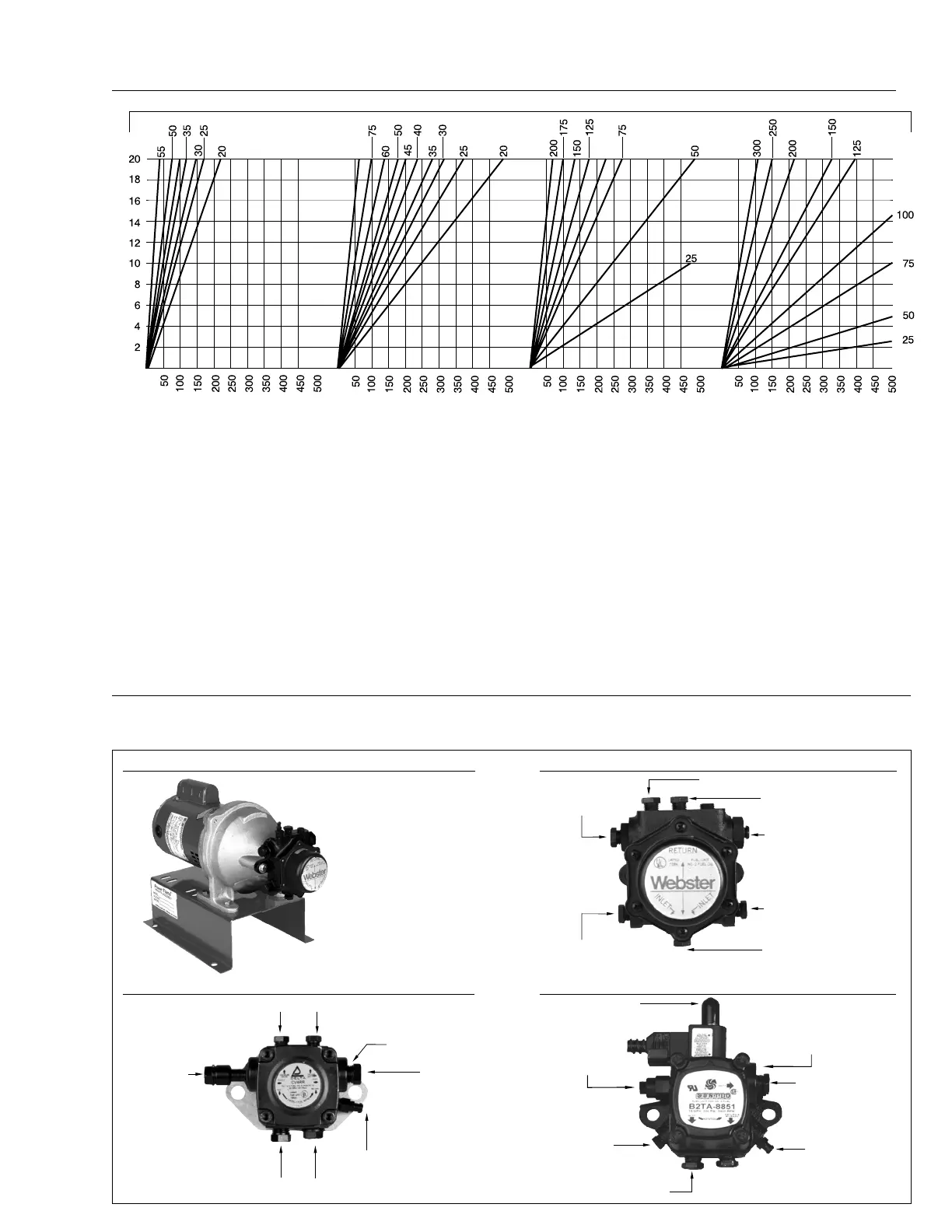
Figure 10
Oil Line Sizing
Suction Capacity in G.P.H.
Inches of Vacuum at Fuel Unit
Total Feet of
3
/8" O.D.
Copper Tube #2 Fuel Oil
Total Feet of
1
/
2
" O.D.
Copper Tube #2 Fuel Oil
Total Feet of
5
/
8
" O.D.
Copper Tube #2 Fuel Oil
Total Feet of
3
/
4
" O.D.
Copper Tube #2 Fuel Oil
1. Check oil pump GPH Suction Capacity shown in Table 6.
2. Measure total tube length (horizontal and vertical) from the
end of the line in the tank, to the connection at the oil pump.
3. Choose the appropriate graph above based on the tubing
size. Read up from horizontal line Total Feet of Copper Tube
to Suction Capacity in GPH.
4. Read left to the vertical line Inches of Vacuum at Fuel-Unit.
(This is the vacuum required to draw oil through the length
of tubing selected.)
5. If installation has lift (Lift is defined as the vertical distance
the fuel unit is above the top of the tank,) add 1" of vacuum
for every foot of lift.
6. Add the vacuum determined from items 4 and 5 together
to determine total inches of vacuum.
7. If total is over 10", move to next larger tubing size chart and
re-calculate total inches of vacuum.
8. The instructions above do not allow for any added
restrictions, such as line filter, elbows, sharp bends, check
valves, etc. Suction line vacuum values for such compo-
nents vary by manufacturer.
A Rule of Thumb to determine total vacuum for suction line
sizing is to add 10% to vacuum determined from Figure 10
calculations.
9. It is always safe to size the return line from pump to tank at
the same size as the selected suction line.
DIRECT DRIVE OIL PUMP
DELTA OIL PUMP DETAIL
WEBSTER 3450 RPM BLOWER MOTOR DRIVEN OIL PUMP
SUNTEC TWO STEP PUMP DETAIL
Piping connection
may not be identical
to blower motor
driven pump. See
pump information
supplied with burners.
Pressure Gauge Port
1
/
8
” NPT
Vacuum Port
1
/
8
” NPT
Nozzle Port
1
/
8
” NPT
Pressure
Regulator
Inlet Port
1
/
4
” NPT
Inlet Port
1
/
4
” NPT
Return Port
1
/
4
” NPT
Vent
Regulator Setting
(with Solenoid De-Energized)
(Low Pressure)
Nozzle Port
1
/
8
” NPT
Pressure
Gauge Port
1
/
8
” NPT
Inlet
1
/
4
” NPT
Inlet
1
/
4
” NPT
Regulator Setting
(with Solenoid Energized)
(High Pressure)
Easy Flow
Air Bleed Valve
Nozzle Port
1
/
4
” NPT
Optional Inlet
1
/
4
” NPT
Optional Inlet
1
/
4
” NPT
1
/
8
” Allen Screw Under
Cover Screw for Nozzle
Pressure Setting
Pressure Gauge Port (or Air Bleed)
Optional Return Port
1
/
4
” NPT
Optional Return Port
1
/
4
” NPT
Figure 11
Oil Pump Details
The oil pumps depicted in this section represent the
most commonly used models. For models not depicted,
such as the Suntec Model J or H, refer to the pump
manufacturer’s bulletin that is supplied with the burner.
C12
Rev.304