Model CR
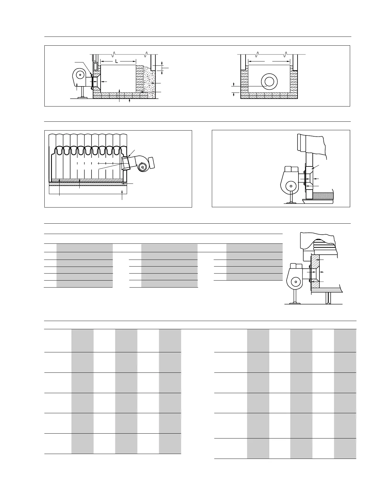
Insulation
1
1
/
2
”
Recess or
Flush
6-8”
Loose Insulation
#1 Firebrick
Insulating Firebrick (2600
o
)Magnesia Block or Equivalent
C
W
See Table 7
for Dimensions
#1 Firebrick
Figure 13
Conventional Firebox Boiler
300 34"
350 38"
400 42"
450 42"
100 22"
125 22"
150 24"
200 28"
250 34"
BHP Min Inside Dimension
20 14"
30 16"
40 16"
60 19"
80 20"
BHP Min Inside Dimension
BHP Min Inside Dimension
C of Door Opening
L
10
o
- 15
o
Sheet Metal Sleeve
Two
1
/
2
” Layers Millboard.
Joints Staggered, Laid
Opposite Direction
1
/
2
” Magnesia Block
2
1
/
2
” - 4” Calcined Aggregate
Laid Loose, No Bond
Aggregate Fill (Washed
Gravel)
3
/
8
” -
1
/
2
” Size
NOTE:
On oil and gas/oil burners
an oil weep hole is located
in the bottom section of the
blast tube next to the
choke ring. Make certain
that the refractory is
constructed such as to
allow oil to evacuate
through this hole into the
combustion chamber
area.
Refractory
Insulation
Fill
Figure 14
Typical Firedoor Installation - Cast Iron Boiler
Figure 15
Packaged Firebox Boiler
Figure 16
Scotch Marine Boilers
Scotch Marine Boiler Minimum Furnace Tube Inside Dimensions
Note: The above minimum dimensions are recommended. If boiler dimensions are less, consult with factory.
All burners set through refractory with sleeve to allow field removal. Unlined space between sleeve and
burner blast tube closed with non-asbestos high-temp rope or KA-O-Wool.
1
1
/
2
” Recess
or Flush
Refractory
1
1
/
2
”
Recess
or Flush
Insulation
Table 7
Suggested Firebox Boiler Combustion Chamber Dimensions
Oil (C)
Gas Input Minimum
Model Input GPH (W) (L) Tube
Number MBTU Hr. #1,#2 Oil Width Length Height
300 2.5 13 17 3
500 3.5 16 22 3
800 6 19 25 3
980 7 20 28 3
700 5 13 17 3
900 6.5 20 28 3
1150 8 22 30 3
1260 9 23 33 3
1000 7 21 29 5
1300 9 23 33 5
1600 13 25 38 5
2100 15 27 42 5
1500 11 25 38 5
2000 14 27 42 5
2500 18 29 46 5
2900 22 30 48 5
2400 17 27 44 5
3300 24 33 53 6
4200 30 37 62 8
5250 37.5 40 68 9
C1-GO-10,
C1-G-10,
C1-O
C1-GO-12,
C1-G-12,
C1-O
C2-GO-15,
C2-G-15,
C2-OA
C2-GO-20,
C2-G-20,
C2-OB
C3-GO,
C3-G,
C3-O
Oil (C)
Gas Input Minimum
Model Input GPH (W) (L) Tube
Number MBTU Hr. #1,#2 Oil Width Length Height
4000 29 35 58 8
5500 40 42 70 9
7000 50 45 76 12
7840 56 48 79 13
6000 43 43 72 10
7500 53 48 79 13
9000 65 50 80 13
10500 75 54 84 15
8000 57 48 79 13
10500 75 54 84 15
12500 89 60 90 17
14215 101.5 64 95 18
12500 89 60 90 17
14000 100 64 95 18
15500 110 68 100 20
17000 121.4 71 110 23
17700 126.4 72 112 25
14000 100 64 95 18
15500 110 68 100 20
17500 125 72 110 24
C4-GO
-30,
C4-G-30,
C4-OA(B)
C5-GO-30(B),
C5-G-30(B),
C5-O(B)
C6-GO-30,
C6-G-30,
C6-O
C7-GO-30(B),
C7-G-30(B),
C7-O(B)
C8-GO-30,
C8-G-30,
C8-O
Note: These dimensions are to serve as a guide only, and may
be modified providing approximate area is maintained.
C14
Rev.304