1
5 6
2
3
7
84
Table 3A
Correction Factors
Table 3
Capacity of Pipe - Natural Gas (CFH)
With Pressure Drop of 0.3” w.c. and Specific Gravity of 0.60
Pipe Length Pipe Size - Inches (IPS)
In Feet
11
1
/
4
1
1
/
2
22
1
/
2
34
10 520 1050 1600 3050 4800 8500 17500
20 350 730 1100 2100 3300 5900 12000
30 285 590 890 1650 2700 4700 9700
40 245 500 760 1450 2300 4100 8300
50 215 440 670 1270 2000 3600 7400
60 195 400 610 1150 1850 3250 6800
70 180 370 560 1050 1700 3000 6200
80 170 350 530 990 1600 2800 5800
90 160 320 490 930 1500 2600 5400
100 150 305 460 870 1400 2500 5100
125 130 275 410 780 1250 2200 4500
150 120 250 380 710 1130 2000 4100
175 110 225 350 650 1050 1850 3800
200 100 210 320 610 980 1700 3500
Note: Use multiplier at right for other specific gravities and pressure drops.
Specific Gravity
Other Than 0.60
Specific Multiplier
Gravity
0.50 1.10
0.60 1.00
0.70 0.926
0.80 0.867
0.90 0.817
1.00 0.775
Propane - Air
1.10 0.740
Propane
1.55 0.662
Butane
2.00 0.547
Specific Drop
Than 0.3
Pressure Multiplier
Drop
0.1 0.577
0.2 0.815
0.3 1.00
0.4 1.16
0.6 1.42
0.8 1.64
1.0 1.83
2.0 2.58
3.0 3.16
4.0 3.65
6.0 4.47
8.0 5.15
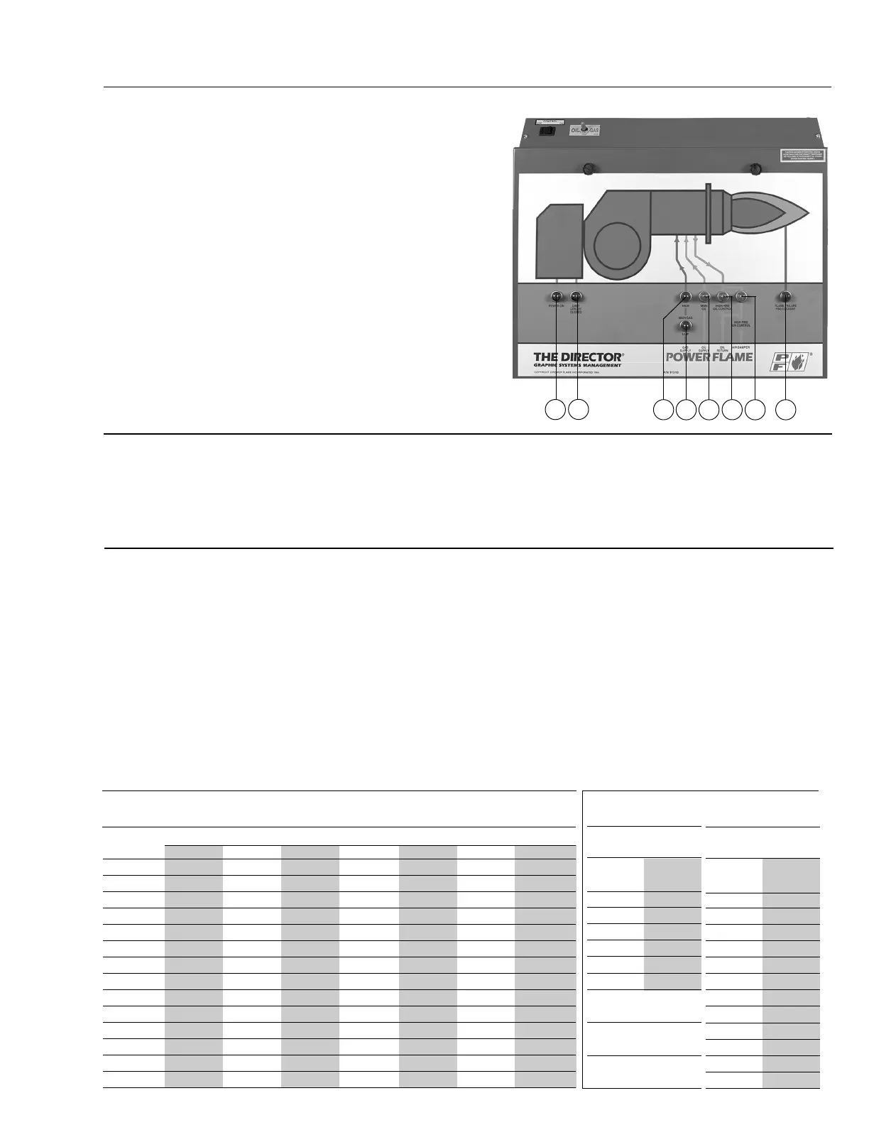
Figure 7
The Director
®
Annunciation System
The Director
®
Annunciation System Mounted on
removable Total Access front panel door, complete with
quick disconnect electrical connection. The Director can
be removed from the panel box (see above) and kept in
operating mode by using the extended length umbilical
cord between the Director and panel box connections.
Annunciation Legend for Gas/Oil Burner with Low-High-
Low Operating Mode
1. Power On
2. Limit Circuit Closed
3. Flame Failure (Flame Safeguard Lockout)
4. Main Gas Valve - Low Position
5. Main Gas Valve - High Position
6. Main Oil Valve
7. High Fire Oil System
8. High Fire Air System
INSTALLATION
The installer should contact the local gas utility relative
to available supply pressures, limitations on allowable
pressures in the building, general piping requirements
and applicable codes, restrictions and regulations.
Considerations of these types, as well as written
permits and other state, city and local codes, should be
discussed with and approved by the appropriate
governing bodies.
GAS SUPPLY PIPING
Gas piping should be sized to provide required pressure
at the burner train inlet manual shutoff cock, when
operating at the maximum desired fuel input.
All gas piping should be appropriately pressure tested to
ensure leak free operation. It is recommended that a dirt
pocket or trap be piped into the gas supply system just
ahead of the burner train inlet manual shutoff cock.
When testing with pressures higher than the maximum
pressure ratings of the gas train components, be sure to
isolate these components and test their piping for gas
leaks with correct pressures only. On some burners, the
maximum main gas train and/or pilot gas train compo-
nents pressure is
1
/2 psig. (14" W.C.).
Refer to Table 3 for information relating to the sizing of
gas supply piping. These charts are based on the
general flow characteristics of commercially produced
black wrought iron pipe. If in doubt regarding flow
capabilities of a chosen line size, the next largest size
is recommended.
Refer to page 10, Figures 8 and 9 for typical gas piping
schematics to meet U.L. requirements in the C burner
firing ranges.
C9
Rev.304