facturer’s bulletin shipped with the burner. It is also stron-
gly suggested that all test procedures outlined in the flame
safeguard control manufacturer’s bulletin be conducted.
37. Complete the Burner Start Up Information and
TestData sheets on pages 46 and 47.
7. SERVICING AND COMPONENT ADJUSTMENTS
General Information on Internal Bypass Oil Nozzle Systems
1. The system is designed to use 300 PSI pressure at the
nozzle inlet at low and high fire (and throughout the
range on modulating systems). The firing rate is changed
by an adjustable bypass arrangement that allows more
or less oil to bypass the nozzle and flow to the return line.
Low fire pressures at the bypass pressure test tee will
generally be from 60 to 100 PSI, with high fire bypass
pressures from 180 to 225 PSI. These pressures will vary
depending upon the nozzle size selection and specific
job firing conditions. See this page, Table 8 for flow rates,
sizing and pressure information.
2. Smoky fires with apparent large droplet size in the spray
pattern are generally caused by low nozzle or return flow
pressures. To properly check the system, it is necessary
to verify both nozzle supply and return pressures. Also
check to make certain that the nozzle adapter and
strainer are not partially plugged.
3. Careless cleaning or handling of the nozzle may
damage the orifice, causing heavy streaks in the oil
spray. This will also show up as large droplets or sparks
in the flame.
4. Off center fires, low bypass line pressures and safety
lockouts (due to poor spray pattern and ignition failure)
may result from plugged slots in the nozzle distributor
head. When such situations are observed, the
nozzle should be removed, disassembled and
cleaned.
5. Excessive after squirt of oil is caused by air in the
system. Be sure air is not trapped in pressure
gauges, overhead oil lines or fittings. A leaking
check valve on the bypass return line from the
nozzle can create the same effect.
6. The Teflon seal should stay on the nozzle when
servicing. On some sizes of burners using Delavan
30630 and 30637 Series nozzles, the Teflon seal
stays in the nozzle adapter. If it is damaged
through careless handling, the resulting leak will
cause an increase in the burning rate, when the
bypass line is closed at high fire.
7. High turn down ratios are a distinct advantage of
internal bypass systems. It is possible, however,
to adjust for a low fire so small that the flame is
being chilled. The fire will look excellent and
appear bright and uniform, but a combustion
efficiency test will reveal high smoke content and
low CO
2
. To correct this situation, increase the oil
flow or decrease the air, or both. Be sure to test
with proper instruments to ensure good, clean
efficient combustion throughout the firing range.
HAGO
Nozzle Size
100 PSIG
Nominal
Rating GPH
#2 Fuel Oil
By-Pass
(Return)
Closed
Approx. High
Fire Rate
GPH
300 PSIG
By-Pass
(Return)
Closed
Approx. High
Fire By-Pass
(Return)
Pressure
PSIG By-Pass
(Return)
Closed
Approx.
By-Pass
(Return)
Pressure
PSIG
Approx.
Firing Rate
GPH
Approx.
By-Pass
(Return)
Pressure
PSIG
Approx.
Firing Rate
GPH
Approx.
By-Pass
(Return)
Pressure
PSIG
Approx.
Firing Rate
GPH
Supply Pressure to Nozzle 300 PSIG at All Rates*
Reduced Firing Rates
4.5 7.3 207 180 5.5 150 4.4 120 3.1
5.0 8.5 196 150 5.9 120 4.4 90 2.8
5.5 9.0 209 180 7.0 150 5.2 120 3.8
6.0 10.2 190 150 7.0 120 5.1 90 3.1
6.5 10.8 195 150 7.6 120 5.2 90 3.4
7.0 11.5 202 150 7.1 120 5.1 90 3.5
7.5 12.6 181 150 10.0 120 7.1 90 4.8
8.0 13.3 197 180 11.6 150 8.2 120 5.5
9.0 15.2 200 180 12.5 150 8.9 120 6.0
9.5 15.9 178 150 12.0 120 8.0 90 5.1
10.0 17.2 202 180 13.8 150 9.6 120 6.3
Table 8
Internal Bypass (Return Flow) Nozzle Data
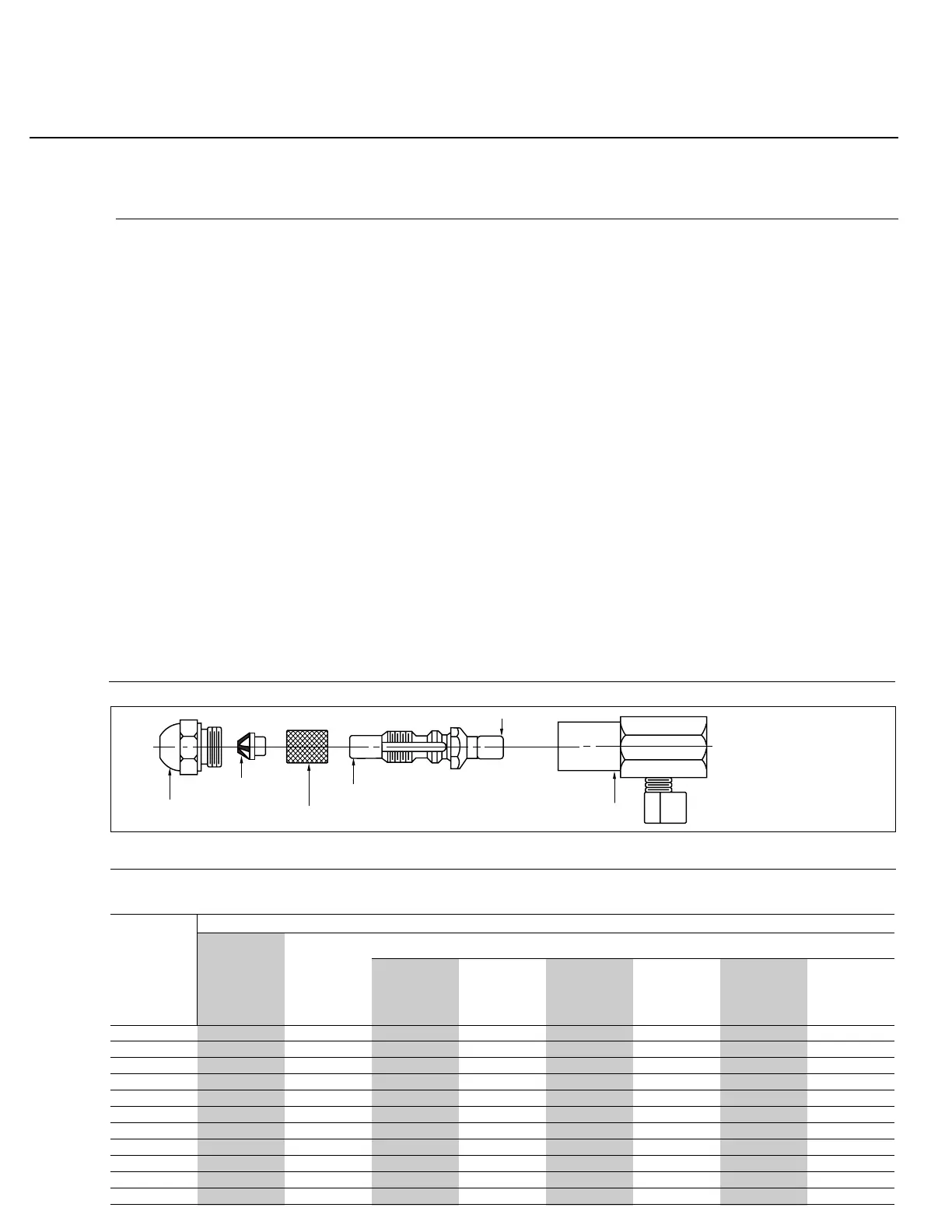
Figure 29
Internal Bypass Oil Nozzle Components
Nozzle Tip
Distributor
Strainer
Combination Locknut & Strainer Support
Seal Bushing
Adapter
C31
Rev.304