Table 9
OIL NOZZLE FLOW RATES
Simplex Nozzle System (Monarch PLP or Equivalent Solid or Semi Solid)
Flow Rate vs Pressure
Oil Nozzle Servicing
1. Nozzles used on Power Flame Type C burners are of two
types: simplex and internal bypass. The simplex nozzle
is normally used on smaller burners in the three to eight
gallons per hour range. The bypass nozzle is used for
larger inputs requiring higher turndown or more
sophisticated air/fuel control. Both types of nozzles have
GPH ratings stamped on the side. Stamped ratings are
based on 100 psig except models 30630 and 30637
which are based on 300 psig. The burners operate in the
300 psig range. See pages 31 through 34, Tables 8 and
9 for flow rates, pressure and sizing information.
2. When removing or replacing the oil nozzle and electrode
assembly, take care to prevent damage to the ignition
wire.
3. The nozzles should be removed from the nozzle adapter
by use of the proper wrench. They should be disas-
sembled and thoroughly cleaned with a liquid solvent
(preferably non-flammable) and a brush.
4. Do not use a screwdriver, wire brush or similar metallic
objects to clean nozzles. Damage to orifices or spray
slots result in off-center or sparky fires.
5. The nozzle should be seated firmly in the nozzle
adapter to prevent leaks.
6. If a nozzle is damaged or burned, replace it.
7. The entire oil tube and nozzle assembly (the oil drawer
assembly) may be removed for ease of service.
8. When cleaning and taking the nozzle apart, do not
force it.
9. For additional information on bypass nozzles, see
page 31. Note that the Teflon seal in the Monarch
F80BPS and Delavan 33769 nozzles is an integral
part of the nozzles and that if the seal is removed
accidentally, the nozzle must be replaced. On the
Delavan 30630 and 30637 nozzles, the seal normally
remains in the nozzle adapter. When the nozzle is
removed from the adapter, the seal should also be
removed and replaced with a new seal.
Oil Pump or Oil Flow Problems and Typical Solutions
NO OIL DELIVERED
1. Reversed pump rotation
2. Suction lift too high (See page 12, Figure 10)
3. Air leak in suction line
4. Pump not primed, or has lost prime
5. Pump coupling not installed properly
6. Pump defective
7. Line plugged
8. Valve closed
NOISY PUMP
1. Air leak in suction line
2. Pump not securely mounted
3. Vibration caused by bent shaft or misalignment
4. Pump overloaded
5. Suction line vacuum so high that vapor forms
within the liquid (see page 12, Figure 10)
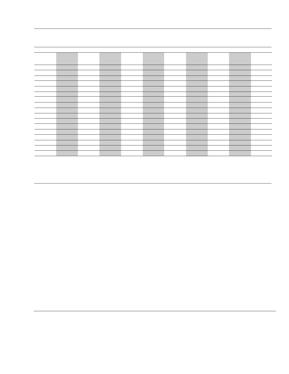
Capacity in GPH #2 Oil
100#
Nominal
Rating
2 2.1 2.3 2.4 2.6 2.7 2.9 3.0 3.1 3.2 3.3
2.5 2.6 2.8 3.0 3.2 3.4 3.6 3.7 3.8 4.0 4.1
3 3.2 3.4 3.6 3.8 4.0 4.2 4.4 4.7 4.8 5.0
3.5 3.7 3.9 4.2 4.5 4.7 4.9 4.2 5.4 5.8 5.9
4 4.2 4.5 4.8 5.1 5.4 5.6 5.9 6.2 6.4 6.7
4.5 4.7 5.0 5.4 5.7 6.1 6.3 6.6 7.0 7.2 7.4
5 5.3 5.6 6.0 6.4 6.8 7.1 7.3 7.7 7.9 8.2
5.5 5.7 6.1 6.5 7.0 7.3 7.7 8.0 8.4 8.6 9.1
6 6.3 6.7 7.2 7.7 8.1 8.5 8.8 9.2 9.5 9.9
6.5 6.8 7.2 7.9 8.3 8.8 9.2 9.5 10.0 10.3 10.7
7 7.3 7.9 8.3 9.0 9.4 9.9 10.3 10.7 11.2 11.4
7.5 7.8 8.5 8.9 9.6 10.0 10.5 11.0 11.5 11.9 12.2
8 8.3 9.1 9.5 10.3 10.8 11.3 11.8 12.3 12.8 13.0
9 9.4 10.1 10.8 11.5 12.0 12.8 13.2 13.9 14.4 14.8
10 10.4 11.2 12.0 12.8 13.4 14.2 14.7 15.4 16.0 16.6
11 11.5 12.5 13.3 14.2 15.0 15.6 16.2 17.0 17.7 18.2
12 12.5 13.6 14.5 15.3 16.2 17.0 17.7 18.5 19.2 19.8
120# 140# 160# 180# 200# 220# 240# 260# 280# 300#
C34
Rev.304