Field Piped
Gas Supply
Pilot
Shutoff
Cock
Vent to Atmosphere as Permitted by Code
Main Gas
Shutoff
Cock
Low Gas
Pressure
Switch
High Gas
Pressure
Switch
N.O.
Vent Valve
Dirt Leg with Cap
Extend to Floor
Main Gas
Pressure
Regulator*
Auxiliary
Gas Valve
Field Piped
Pilot
Solenoid
Valve
Pilot Gas
Pressure
Regulator
Gas Pilot
Ignitor
Gas Burner
Manifold
Leakage
Test Cock
Orifice Tee
Main
Gas Valve*
(With Pressure Tap; May
be in Nipple or Test Cock)
May be omitted on U.L. listed
units not exceeding 5,000 MBH
when proof of closure system is
furnished.
Denotes not required below
2,500 MBH.
Proof of closure feature
required above 5,000 MBH.
N.O. vent valve required above
12,500 MBH.
All On-Off units completely field
piped.
Field Piped
Gas Supply
Pilot
Shutoff
Cock
Vent to Atmosphere as Permitted by Code
Main Gas
Shutoff
Cock
Low Gas
Pressure
Switch
High Gas
Pressure
Switch
N.O.
Vent Valve
Dirt Leg with Cap
Extend to Floor
Main Gas
Pressure
Regulator*
Auxiliary
Gas Valve
Field Piped
Pilot
Solenoid
Valve
Pilot Gas
Pressure
Regulator
1
/
8
”
Pressure
Tap
Gas Pilot
Ignitor
Gas Burner
Manifold
Leakage
Test Cock
1
/
4
” Pressure Tap
Main
Gas Valve*
(With Pressure Tap; May
be in Nipple or Test Cock)
May be omitted on U.L. listed
units not exceeding 5,000 MBH
when proof of closure system is
furnished.
Denotes not required below
2,500 MBH.
Proof of closure feature
required above 5,000 MBH.
N.O. vent valve required above
12,500 MBH.
Butterfly Valve
(Operated by
Modulating Motor)
1
/
8
”
Pressure
Tap
1
/
4
” Pressure Tap
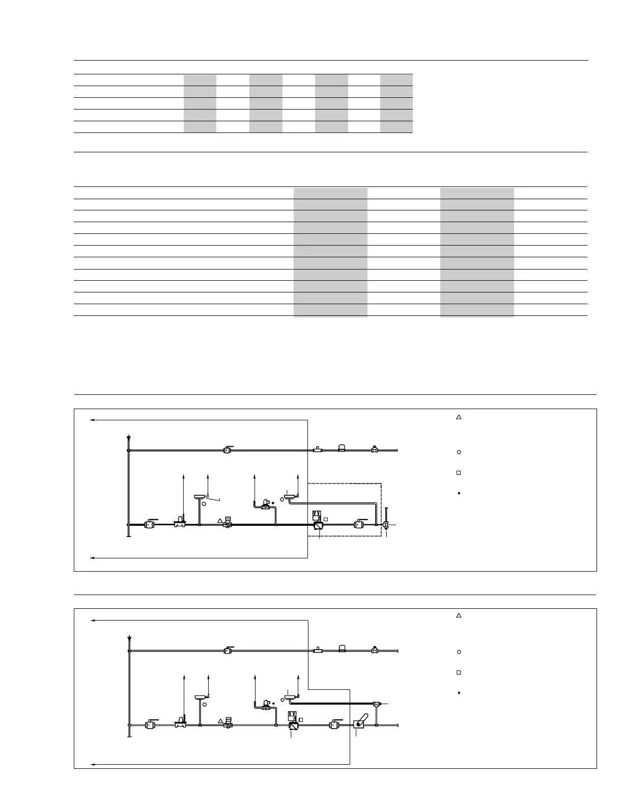
Figure 9
Typical Schematic Gas Piping for Type C Burner, Modulating System
Figure 8
Typical Schematic Gas Piping for Type C Burner, On-Off, Low-High-Off and Low-High-Low System
**
**
Table 4
Equivalent Length of Fittings in Feet
1. Supplied as standard on inputs of 2,500,000 BTU/hr. and
above. Available as an option below 2,500,000 BTU/hr. inputs.
2. Supplied as standard on inputs of 5,000,000 BTU/hr. and
above. Available as an option below 5,000,000 BTU/hr. inputs.
* Certain burners will have a combination pressure regulator/
diaphragm gas valve in lieu of a separate regulator and valve.
Canadian electrical and fuel codes require systems that
vary from the above. Consult the factory for specific details.
Table 5
Gas Train Components Supplied for Standard U.L. Burner Requirements
Fuel Air Control Modes of Operation On/Off Low/High/Off Low/High/Low Modulating
Main Gas Cock XU XU XU XU
Main Gas Pressure Regulator XU* XU XU XU
High and Low Gas Pressure Switches OU X
1
UX
1
UX
1
U
Automatic Main Gas Valve XU* X X XU
Automatic Main Gas Valve with Proof of Closure OX
1
X
1
X
1
Main Auxilary Gas Valve OX
2
X
2
X
2
Leak Test Gas Cock XU X X XU
Pilot Cock, Pressure Regulator & Solenoid Valve XXX X
Modulating Butterfly Valve N/A N/A N/A X
Side Tee Orifice Assembly X X X N/A
Main and/or Pilot Gas Pressure Gauge OOO O
See Gas Flow Schematics this page, Figure 8 and 9 for additional information
X - Supplied as standard O - Optional N/A - Not available (U) - Unmounted
* On some burner models at inputs below 2500 MBH a combination pressure regulator/automatic gas valve may be used in place of the separate main gas
pressure regulator and main gas shutoff valve shown in Figure 8 and 9 above. For specifics on your burner refer to the gas piping diagram supplied with the
burner.
Pipe Size (IPS) 1 1.25 1.5 2 2.5 3 4
Std. Tee through Side 5.5 7.5 9.0 12.0 14.0 17.0 22.0
Std. E11 2.7 3.7 4.3 5.5 6.5 8.0 12.0
45
o
E11 1.2 1.6 2.0 2.5 3.0 3.7 5.0
Plug Cock 3.0 4.0 5.5 7.5 9.0 12.0 16.0
C10
Rev.304