C11
Rev.304
1. The standard pump normally supplied is 19 GPH for On-Off
or Modulating and 40 GPH for fixed air low fire start,
Low-High-Off and Low-High-Low operation. Optional
pumps are available which, depending on model specified,
could be as high as 70 GPH. Refer to information shipped
with the burner and/or consult the factory for specifics.
2. The standard pump normally supplied is 40 GPH for Low-
High-Off and Low-High-Low and 70 GPH for On-Off and
Modulating operation. Optional pumps are available for
Low-High-Off and Low-High-Low which could be as high
as 70 GPH. Refer to information shipped with the burner
and/or consult the factory for specifics.
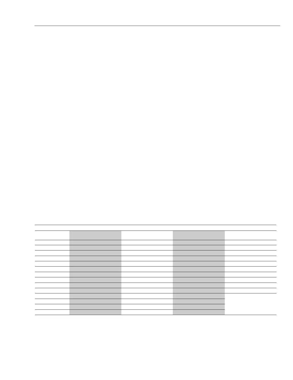
Table 6
Oil Pump Suction Capacity and Filter Selection Chart
Gas/Oil Model Oil Model GPH Power Flame Alternate
Suction Capacity Oil Filter Model Oil Filter
C1-GO-10 70(1) 73410 (Fulflo FB-6)
C1-GO-12 C1-O and C1-OS 70(1) 73410 (Fulflo FB-6)
C2-GO-15 C2-OA and C2-OAS 70(2) 73410 (Fulflo FB-6)
C2-GO-20A C2-OB and C2-OBS 40 70101-100 73410 (Fulflo FB-6)
C2-GO-20B C2-OB and C2-OBS 40 70101-100 73410 (Fulflo FB-6)
C3-GO-20 C3-O 105 70101-100 73410 (Fulflo FB-10)
C3-GO-25 C3-O 105 70101-100 73420 (Fulflo FB-10)
C3-GO-25B C3-O(B) 135 70101-100 73420 (Fulflo FB-10)
C4-GO-25 C4-OA 135 70101-100 73420 (Fulflo FB-10)
C4-GO-30 C4-OB 135 70101-100 73420 (Fulflo FB-10)
C5-GO-30(B) C5-O(B) 250 70101-100 73290 (#72 1” Hayward
C6-GO-30 C6-O 250 70101-100 with 100 mesh basket)
C7-GO-30(B) C7-O(B) 265 70101-100 73290 (#72 1” Hayward
C8-GO-30 C8-O 265 70101-100 with 100 mesh basket)
73290 (#72 1” Hayward
with 100 mesh basket)
OIL SUPPLY PIPING
The C burner is designed for use with light grade fuel oils
- commercial standard grades #2 or #1.
It is recommended that prior to installation all national,
local and other applicable codes be reviewed to ensure
total compliance.
It is recommended that prior to installation, NFPA-31 and
all other national, state, local and other applicable codes
be reviewed to ensure total compliance with their
requirements including, but not necessarily limited to, the
use of anti-syphon valve(s), oil safety valve(s) (OSV), or
other acceptable means to prevent siphoning of the oil
when tank is above burner level. Even if such devices
are not required by code, they should be considered
good installation practice and mandatory when the tank
is above burner level.
Do not install manual valves in the return line between
the pump and the tank unless required by a specific
code. If a manual valve is required, an automatic relief
valve must be installed across the manual valve to
ensure that oil will bypass directly back to the tank in the
event the manual valve is inadvertently left in the closed
position.
Use copper tubing with flare fittings or iron pipe on all
installations. All units must utilize the proper size and
type of suction line oil filters. See this page, Table 6 for
recommended Power Flame oil filters.
If the oil storage system has been used with fuel heavier
than #2 fuel oil, the entire system should be thoroughly
cleaned and flushed before starting up the new system.
Utilize fusible link and/or overhead anti-siphon valves as
appropriate.
If iron pipe oil lines are used on underground tanks, swing
joints utilizing nipples and elbows must be used and
joined together, making certain the piping connections
are tightened as the tank settles. Keep swing joints in the
suction and return lines as close to the tank as possible.
Underground tanks should be pitched away from the
suction line end of the tank to prevent sediment from
accumulating at the suction line entrance. The suction
line should be a minimum of 3" from the tank bottom.
Before starting up the system, all appropriate air and oil
leak tests should be performed. Make certain that the tank
atmospheric vent line is unobstructed.
Refer to page 12, Figure 11 for fuel pump oil piping
connection information. Further information relating to
burner oil piping can be found in Table 6 this page, Figure
11 on page 12, and Figure 12 on page 13.
It is very important to properly size the oil suction line and
oil filter, to provide fuel flow to the burner without exceeding
10" suction pressure (vacuum) at the oil pump suction
port. The method to properly size copper tubing is outlined
on page 12 (Figure 10). Consult Power Flame Customer
Services Department for sizing assistance regarding
iron pipe.