require a spark ignited gas pilot* to provide ignition for the
main oil flame. The nozzle oil flow rate is set by adjusting
the Oil Pump Pressure Regulating Valve (3). Turn clock-
wise to increase the pressure and counter-clockwise to
decrease the pressure to the Nozzle. Normal nozzle
pressure will be 100 to 300 PSI. Refer to page 33, Table
9 to determine specific nozzle pressures and firing rates.
Nozzle pressures are taken at the plugged Nozzle Pressure
Gauge Port (6). The oil on-off flow to the Nozzle is controlled
by the Oil Solenoid Valve (1). The Air Dampers (4) are
adjusted and locked in place with the Air Damper Arms (5).
The burner operates at one fixed firing rate. See page 12,
Figure 11 and pump manufacturer’s bulletin packed with
the burner for more information.
* Not shown in this depiction. See page 3, Figure 1.
Note 1
Component operational sequencing will vary with the specific
Flame Safeguard Control being used. Refer to the specific Flame
Safeguard Control bulletin supplied with the burner for complete
information.
Note 2
The system depicted above is based on the use of an oil pump
manufactured by COMBU Incorporated. If your system uses other
than a COMBU pump, refer to the oil piping diagram and oil pump
manufacturer’s bulletin supplied with the burner for specifics
pertaining to your system.
MECHANICAL OPERATION: The On-Off system uses a
single stage, high suction lift Oil Pump (2) with a Simplex
Oil Nozzle. A direct spark oil ignition system is standard
on typical oil burners (a gas pilot is standard on Gas/Oil
burners), but certain insurance company codes could
1
2
3
5
4
4
6
* By Others Unless Specified
on Order.
** Burners with Remote Pressure
Atomizing Oil Pumps require a
Low Oil Pressure Switch.
CAUTION:
All field piped components must be
mounted in the proper location and
proper direction of oil flow.
CAUTION:
Oil supply pressure to Burner Pump
must not exceed 3 PSI per NFPA
Code.
DO NOT USE TEFLON TAPE
9
Nozzle
1
Oil Solenoid
Valves
Field Piped
Low Oil Pressure Switch **
Oil Pump
2
N.O. Low Fire
Solenoid
7
Nozzle Port
Optional
Inlet Ports
Air Bleed
Valves
Return
Port
Inlet Port
Oil
Pump
Side
View
Check Valve
(At Tank)*
Fuel
Shutoff
Valve*
Fusible Link Valve
(If Required By Code)*
Filter*
Check
Valve*
Inlet
Return
To Tank
Field
Piped
3
Pressure Gauge Test
Port
6
Flat Slot Screw-
driver Low Fire
Pressure
Adjustment
Flat Slot Screw-
driver High Fire
Pressure
Adjustment
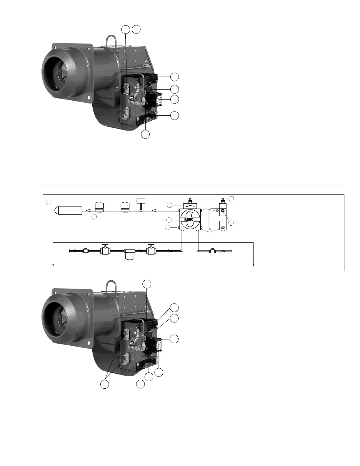
Figure 21
Typical Oil Burner with Fixed Air Low Fire Start Fuel/Air Control Mode
8
For both high and low fires, turn the adjustment screws
clockwise to increase the pressure and counterclockwise
to decrease the pressure to the Nozzle. Approximate low
fire pressures are 150 to 225 psig and high fire, 200 to
300 psig. Remember, you will be lighting off at full air
and reduced fuel. Raise low fire enough to obtain depend-
able light off with these conditions. The Air Dampers (4) are
adjusted and locked in place with the Air Damper Arms (5) for
correct combustion values at the high fire rate. At light off,
the Main Oil Solenoid Valve (1) is energized, allowing
fuel to flow to the Nozzle. The normally open Low Fire
Solenoid Valve (7) allows a reduced amount of oil to the
Nozzle for low fire start. When the flame is proven by the
flame detector*, the low fire solenoid valve closes,
providing full high fire pressure to the Oil Nozzle. The
burner operates at the high fire position until the system
load demand is satisfied. Refer to page 34, Table 9 for
specific nozzle pressures and firing rates. See page 12,
Figure 11 and the pump manufacturer’s bulletin supplied
with the burner for additional information.
* Not shown in this depiction. See page 3, Figure 1.
Note 1
The system depicted uses a two-step Suntec oil pump. If a pump
that does not have the integral two-step function has been
specified and supplied, it will be provided with an N.C. nozzle
bypass oil solenoid valve and a separate adjustable low fire relief
valve. Refer to the oil piping diagram and the oil pump manu-
facturer’s bulletin supplied with the burner for the specifics on
your system.
MECHANICAL OPERATION: The fixed air low fire start
system uses a two-step, two-stage Oil Pump (2) with a
Simplex Oil Nozzle. A direct spark oil ignition system is
standard on typical oil burners (a gas pilot is standard on
Gas/Oil burners), but certain insurance company codes
could require a spark ignited gas pilot* to provide ignition
for the main oil flame. The nozzle flow rate pressures are
taken at the Plugged Pump Nozzle Pressure Gauge Port (6).
The low fire oil flow rate is set by adjusting the Oil Pump
Low Pressure Regulator (8). The high fire oil flow rate is
set by adjusting the Oil Pump High Pressure Regulator (3).
3
Model C-O
8
7
6
1
2
5
4
C17
Rev.304