Gas or Gas/Oil Burner Fuel/Air Premix Adjustment - Gas, Oil or Gas/Oil Burner Diffuser Adjustment
moving it forward decreases the premix air. Generally, the
best (quietest/smoothest) operation is in the full forward
position with minimum premix air. The premix adjustment
is set at the factory in the full forward position. To attain
the best combustion results for specific job conditions,
change position in small increments.
DIFFUSER POSITION ADJUSTMENT
Moving the blast tube diffuser assembly fore or aft on gas
or oil firing will move the flame front (point of retention) in
order to attain the best (quietest/smoothest) combustion
for specific job conditions. If the initial midway point factory
setting does not provide satisfactory results, move fore or
aft in small increments to achieve the best combustion
results. If unit is oil or combination gas/oil, the attached,
flexible copper oil nozzle line will move fore or aft with
the assembly. When firing on oil, moving the assembly
forward will tend to broaden the flame pattern and moving
it back will narrow the flame pattern. Similar results are
obtained on gas, but observation of sound and combus-
tion tests are the best determinants of results on either
gas or oil.
Gas/Air Premix Adjustment Knob
Blast Tube Diffuser Position Adjustment
Gas Inlet
Figure 26
FUEL AIR PREMIX
ADJUSTMENT(OPTIONAL)
The adjustable premix blast tube (optional) incorporates an
adjustable gas/air premix within the burner firing head. The
premix configuration is primarily used for cylindrical combus-
tion chambers or high heat release pressurized fireboxes.
Moving the adjustment knob back increases the premix air;
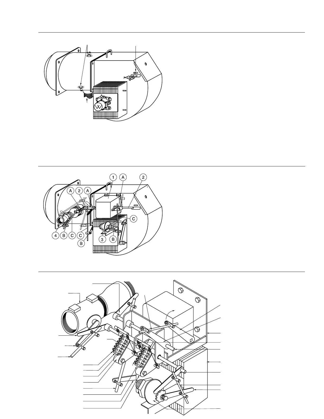
Gas/Oil Linkage Adjustment For Full Modulation Standard System
Typical general linkage arrangement for combination
gas/oil full modulation burner, shown in low fire light
off position. Dotted lines indicate approximately high
fire position. When making adjustments, make certain
the motor can make its full 90
o
stroke without any
linkage binding.
Driver Arms (A) connected to the Modulating Motor (1)
Jack Shaft (2) will increase the travel of the Driven Arms
(B) as the Linkage Rod (C) ball joint is moved away from
the Jack Shaft. The travel of the Driven Arms will be
increased as the Linkage Rod ball joint is moved toward
the shaft of the driven device.
1. Modulating Motor
2. Jack Shaft
3. Modulating V Port Oil Valve
4. Modulating Butterfly Valve
A. Driver Arms
B. Driven Arms
C. Linkage Rods
Figure 27
Air Damper
Driver Arm
Modulating
Butterfly
Gas Valve
Gas Fuel
Driver Arm
Gas Fuel
Driven Arm
Gas Fuel
Linkage Rod
Cam Screw #13
Gas Fuel Cam Arm
Thread Binding Set Screw
Gas Fuel Cam Follower
Cam
Spring
Cam
Screw
#13
Oil Fuel Driven Arm
Oil Fuel Linkage Rod
Oil Fuel Driver Arm
Modulating Motor Bracket
Jack Shaft Driven Arm
Modulating Motor Driver Arm
Open
Modulating
Motor
Jack Shaft
Linkage Rod
Jack Shaft
Figure 28
Gas/Oil - Detail and Adjustments on Modulating Varicam
TM
Characterized Fuel Metering System.
For complete adjustment instructions refer to bulletin
VA1588 Varicam Adjustment Instructions included in
the information shipped with the burner.
Air Damper Linkage Rod
Oil Fuel Cam Follower
Air Damper Housing
Oil Fuel Cam Arm
Air Damper Driven Arm
Modulating Oil Valve
Typical Cam Spring
C22
Rev.304