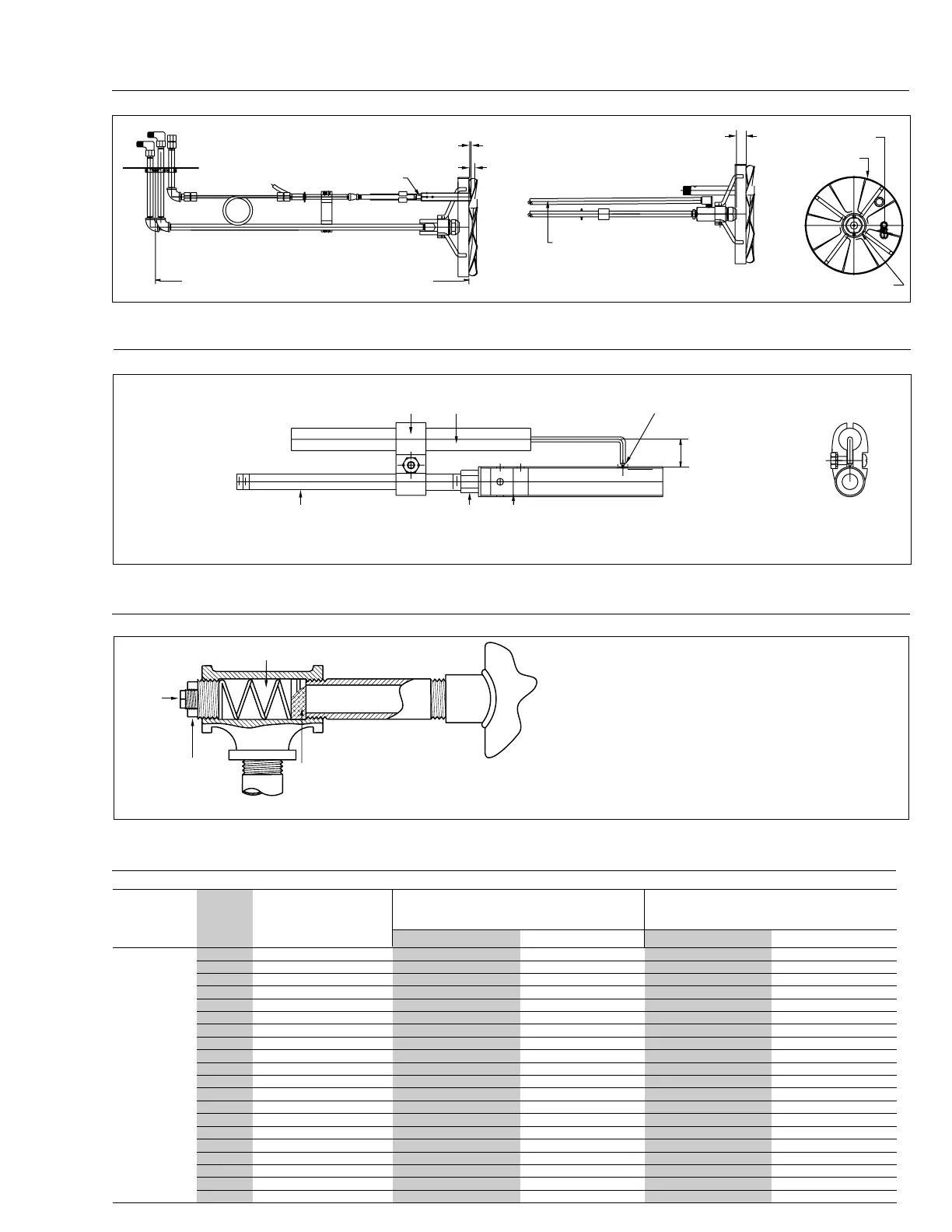
Figure 38
Location of Side Orifice (When Supplied)
Pressure
Test
Point
Plug A
Location of Side
Orifice (When
Supplied)
Orifice Spring
Check to ensure that the side orifice size is correct
according to Burner Specification Sheet. To gain access to
orifice, remove plug A and withdraw spring and orifice.
When replacing orifice, ensure that it seats properly inside
the tee. The spring may be deformed slightly in order to
hold the orifice firmly for insertion.
ORIFICE (A) LIMITING ORIFICE (B) APPROXIMATE ORIFICE PRESSURE
IDENTIFICATION INSIDE DIAMETER INCHES (INCHES W.C.) OR TEE PRESSURE
I.P.S.SHOULDER IF NO ORIFICE SIZE IS SHOWN
NOMINAL O.D. INCHES
250 1
1
/
2
5/16 15/64 3.0 4-5
300 1
1
/
2
11/32 1/4 3.0 4-5
350 1
1
/
2
3/8 17/64 3.0 4-5
400 1
1
/
2
13/32 9/32 3.0 4-5
450 1
1
/
2
27/64 19/64 3.0 4-5
500 1
1
/
2
7/16 5/16 3.0 4-5
550 1
1
/
2
15/32 21/64 3.0 4-5
600 1
1
/
2
1/2 11/32 3.0 4-5
650 1
1
/
2
17/32 23/64 3.0 4-5
700 1
1
/
2
9/16 3/8 3.0 4-5
750 1
1
/
2
19/32 13/64 3.0 4-5
800 1
1
/
2
5/8 13/32 3.0 4-5
850 1
1
/
2
11/16 27/64 3.0 4-5
900 1
1
/
2
25/32 7/16 3.0 4-5
950 1
1
/
2
13/16 29/64 3.0 4-5
1000 1
1
/
2
27/32 15/32 3.0 4-5
1100 1
1
/
2
7/8 31/64 3.0 4-5
1200 1
1
/
2
NONE 1/2 3.0 4-5
1300 1
1
/
2
NONE 17/32 3.5 4-5
1350 1
1
/
2
NONE 35/64 3.8 4-5
Gas Burner Orifice Sizing Information (See this page Figure 38 for side orifice detail.)
Table 10
C1-G(O)
With
Standard
Nozzle
Mix Tube
30 9/64
Figure 36
C7/C8 Gas and Gas/Oil Gun Assembly
* NOTE: Blade Setting May Change For
Specific Boiler Models (Consult Factory)
Side View
Top View
Front
This Pipe omitted on C7 and
C8 Gas Gun Assemblies
1
/
2
” Blade Setting*
+1
/
16
” Blade Tips After Adj.
Must be Within
1
/
16
” of A Flat Plane
-
.875 [
7
/
8
] From Front of Nozzle
Adpt. to Back of Diffuser
Pilot Extends Thru Diffuser 0.125 [
1
/
8
]
5
/
32
” Diameter Orifice
As Shown Fig. 37
9.026 [9
1
/32
]
O.D.
Initial Full Foward Setting 29.000 [29] C7
Initial Full Foward Setting 34.531 [34
17
/
32
] C8
2.250 [2
1
/
4
] I.D.
View
Figure 37
C5B-C8 Gun Mounted Pilot Assembly
Set Tip Flush With Outside
P/N X04222 Ignition Electrode
P/N X04034 Alum Extruded Clamp
P/N X02137 1/8X5
Pipe Nipple
P/N X04350 Pilot Orifice
Drilled 5/32”
P/N F20450 3/4”
Round Pilot Head Assy.
Front View
Side View
2.320 [2
21
/
64
]
BURNER MBTU
MODEL INPUT NATURAL GAS PROPANE GAS NATURAL GAS PROPANE GAS
C37
Rev.304