Page 49 of 80 Instruction Manual for AURORA CDD BCG.00613_AA
Part 4 Operations Guide
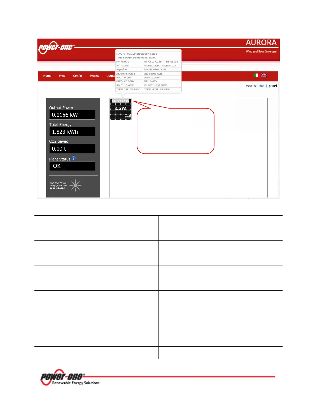
The following information will be displayed in the pop-up window:
MAC RF
: Radio Frequency Mac address
VIN
TIME STAMP
: Date and time of the display
POUT
Fw
RF: Radio Frequency firmware version
EN TOT:
uP
: MICRO inverter firmware version
IOUT:
DSP
VOUT
PN
FREQ
TEMP DSP
: Internal DSP temperature
TEMP MOSF
Signal
: Indicates the radio communication signal
between the CDD and the MICRO inverter
ALARM STAT
: Indicates the number of alarms of
each individual MICRO inverter
BOOST STAT
: It allows 3 states, RUN (booster
operational), START UP (booster awakening) and
PROT (booster into protection)
INV STAT
: It allows 3 states, RUN (booster
generating power), START UP (inverter awakening)
and PROT (inverter into protection)
MODEL DESC
: MICROinverter model description
Click on the serial number
(SN) to open a pop-up
window with individual
information for each