Page 69 of 80 Instruction Manual for AURORA CDD BCG.00613_AA
Part 5 Troubleshooting
5.1 ALARM CODES AND ERROR MESSAGES
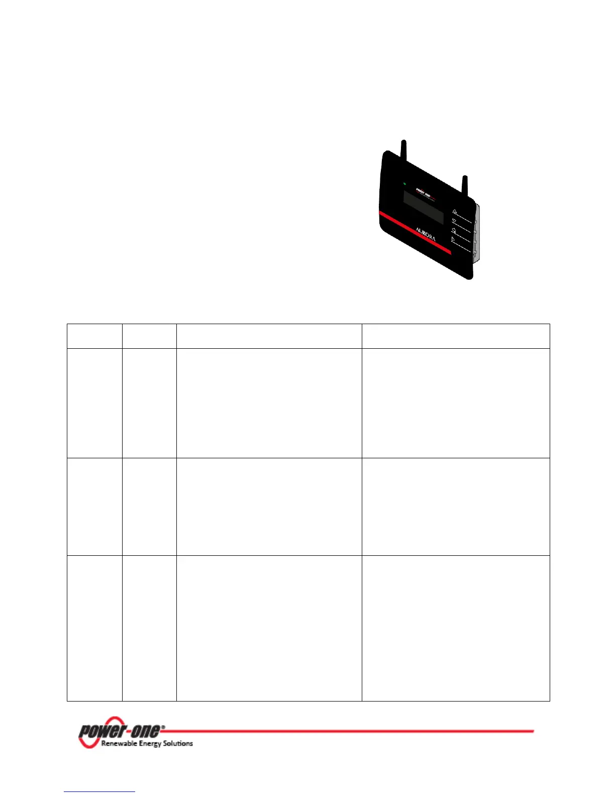
The AURORA MICRO Inverter is capable of
communicating errors/warnings via radio to the
associated CDD device. Any messages received
and related codes can be checked on the display
of the CDD device
Table 5-1
below provides a description of the
alarm messages and error codes.
Table 5-1: Alarm Messages and Error Codes
Alarm
Code
Cause Solution
Input OC E001
The error appears when the inverter input
current exceeds the set overcurrent
threshold. This may be caused by:
a) sudden irradiance
changes that may
generate input current surges into the
MICRO inverter
b) PV module incompatible with the
MICRO-inverter input characteristics
a) The error occurs sporadically and no
action is required as the MICRO-inverter will
automatically reset to normal operation
b) It is necessary to verify that the
photovoltaic module
compatible with the inverter.
c) If conditions a) and b) have been verified
and the error persists, the malfunction may
be caused by an internal inverter fault
Vbulk OV E004
The error is generated when the voltage at
the ends of the bulk capacitors exceeds the
Over Voltage threshold. This may be
caused by:
a) Grid voltage too high
b) Internal inverter fault
a) Check that the grid voltage is compatible
with the MICRO-inverter specifications. In
the event of highly abnormal grid voltage,
please contact your grid operator to address
the problem.
b) If no problems are found when checking
the grid voltage, the alarm may be caused
by internal inverter faults.
Output OC E006
The error appears when the inverter output
current exceeds the internal inverter alarm
threshold.
This may be caused by:
a) High impedance grid with significant
voltage variations, even with small loads.
b) Internal inverter fault
a) Check that the gri
mainly upon:
- loading with high current peak loads.
-
maximum power generation of the PV
system
If the grid voltage is unstable, verify the
appropriate sizing of the line cable/s, and, if
correct, please contact your grid operator to
address the problem.
b) If no problems are found when checking
the grid voltage, the alarm may be caused
by internal inverter faults