10
MOUNTING SAW TO STAND
Tools required
12mm wrench.
Tip: Remove all contents from box except saw and
one extension wing. Put some soft padding on floor
beside box. Fold back carton flaps and gently roll box
upside down on to padding. Lift off box, being care-
ful not to let extension wing fall.
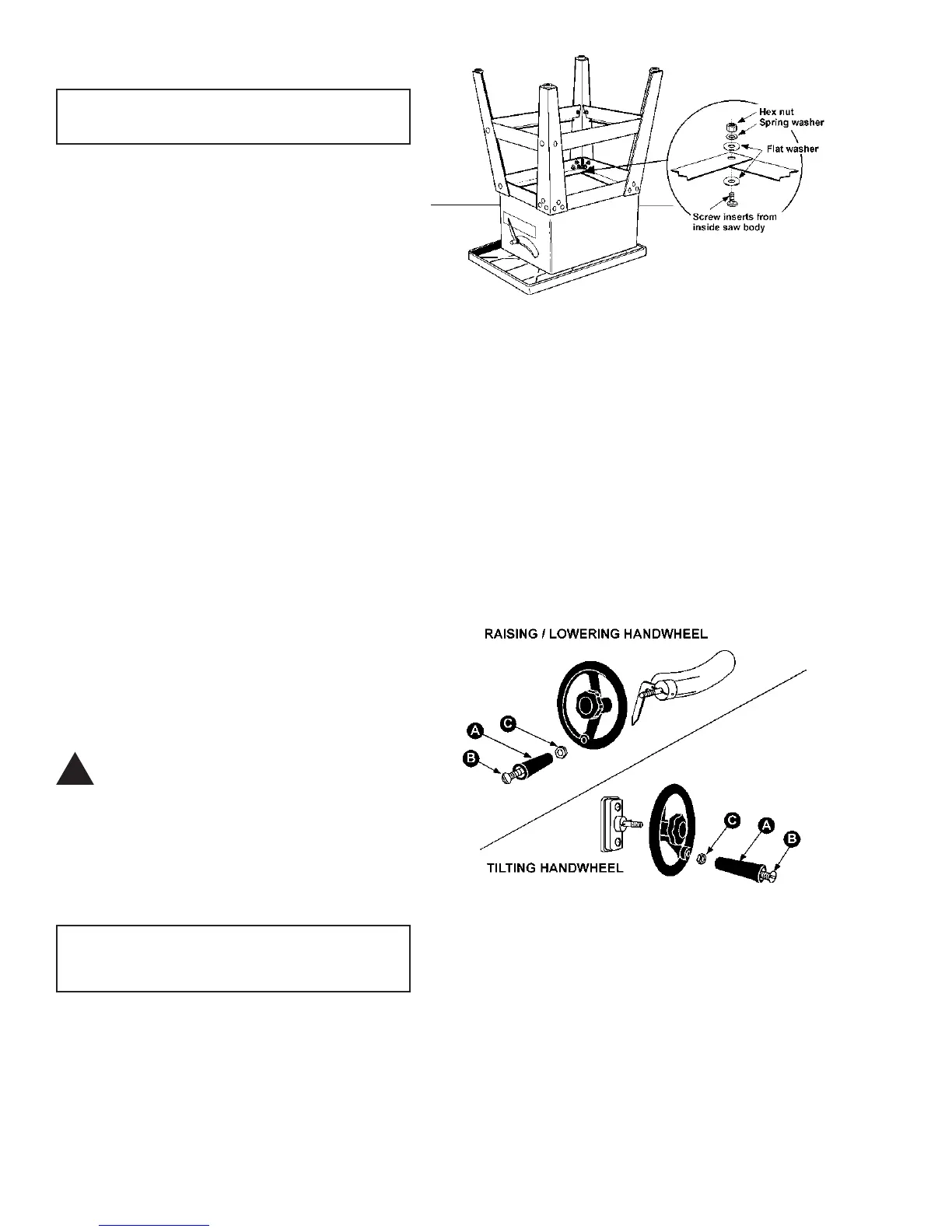
1. Place table top upside down with its surface on
a flat floor, and place stand, with legs upside down,
atop the cabinet. See Figure 4.
2. Align the holes of stand with holes on bottom
flange of saw base and tightly secure with four 5/16-
18 x 1 hex head screws, four 5/16 hex nuts, four 5/16
flat washers, and four 5/16 spring washers. The screw
heads should be inside of the saw body (see inset,
Figure 4).
3. Carefully set the machine to its upright position.
4. With the saw located at the place of operation,
(with a solid foundation), spread the stand legs to self-
align the machine. (If using an optional mobile base,
place the machine onto the base now). When all four
legs are seated solidly on the floor (or base), tighten
down securely all nuts and screws in the stand as-
sembly.
NOTE: If the saw is to be used without the metal
stand provided, care must be taken to provide a hole
in the stand or bench utilized by the operator to facili-
tate the removal of sawdust.
CAUTION: If there is any tendency to slide,
walk, or tip over during operation, the
stand or bench MUST be secured to the
floor.
ASSEMBLING HANDWHEELS
& LOCK KNOBS
Tools required
flat head screwdriver
14mm wrench
1. Attach handwheel knob (A) by inserting screw
(B) through hollow knob and into the 3/8" lock nut (C).
See Figure 5. Lightly screw assembly into handwheel.
2. Tighten the nut (C) to the handwheel just enough
so that there is adequate looseness in the knob (A) to
allow free rotation.
FIGURE 4
FIGURE 5
!