19
45 AND 90 DEGREE POSITIVE STOPS
Tools required
Adjustable wrench (or pliers)
Convenient access to these adjustments will be from
the back side of the saw.
1. Disconnect machine from power source.
2. Raise the saw blade to its maximum height.
3. Set the blade at 90 degrees to the table by turn-
ing the blade tilting handwheel clockwise as far as it
will go.
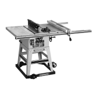
4. Place a square on the table and check to see
that the blade is at a 90 degree angle to the table.
See Figure 26.
5. If blade is not at 90 degrees, proceed as follows:
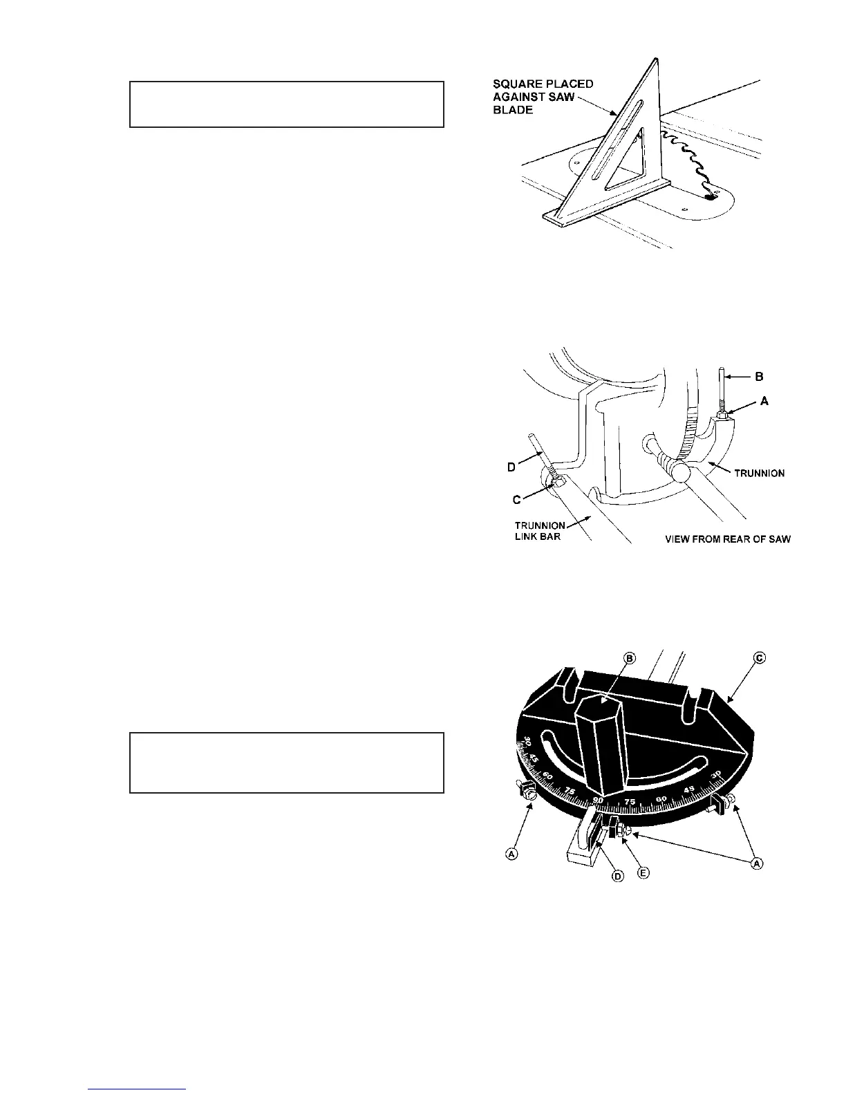
The 90 degree stop is located on the trunnion bracket
toward the front of the saw, Figure 27. Loosen the lock
nut (A) and turn adjusting stop screw (B) with a wrench
until screw contacts the underside of table at the
blade's 90 degree position. Tighten lock nut. Re-check
and adjust as necessary.
6. The stop screw for 45 degrees is located toward
the front of the saw on the cylindrical trunnion link bar,
Figure 27. If the saw is not cutting at 45 degrees,
loosen the lock nut (C) with a 14mm wrench. When
the screw has been loosened, adjust to the proper
position by holding the stop screw (D) with one wrench
while tightening the lock nut (C) with the other.
MITRE GAUGE ADJUSTMENT
Tools Required
8mm wrench
phillips screwdriver
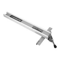
Your mitre gauge is equipped with individually adjust-
able index stops at 90 degrees and 45 degrees right
and left. The index stops can be adjusted by tighten-
ing or loosening the three adjusting screws (A). See
Figure 28.
To operate the mitre gauge, loosen lock handle (B)
and move the body of the miter gauge (C) to the de-
sired angle. The mitre gauge body is set to stop at 0
degrees and 45 degrees left or right. To move the
gauge beyond these points, the stop link (D) must be
flipped out of the way.
FIGURE 26
FIGURE 27
FIGURE 28