12
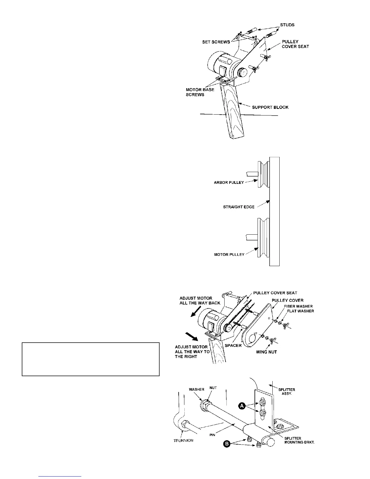
FIGURE 10
6. Install the motor assembly onto the protruding
studs at the back of the saw. See Figure 10.
7. Tighten down setscrews in top of cast motor
bracket with hex wrench as shown in Figure 10.
8. Use an assistant or get a support block (a 2 x 4
for example) approximately 21" to 22" long. Lift motor
up and position block under the motor to support its
weight.
9. Slightly loosen motor base screws.
10. Align pulleys using a straight edge as shown in
Figure 11. NOTE: If a pulley needs to be adjusted on
the shaft, loosen the set screws, slide the pulley for-
ward or back as needed. Re-tighten set screws.
11. Mount the drive belt to the pulleys by raising mo-
tor off the support block. With the drive belt mounted,
lower the motor back to rest on the support block.
12. Position pulley cover seat in line with pulleys,
but not so it will interfere with belt operation.
13. Adjust the motor all the way back on the slots of
the base, then move it all the way to the right. See
Figure 12. This will prevent the motor from rising above
the table when tilted at 45 degrees. Lock down motor
base screws.
14. Remove pulley cover wing nuts with washers and
install pulley cover, as shown in Figure 12, over the
bushing and carriage bolt. Replace the wing nut and
washers and tighten down the pulley cover so that it
fits snugly over the pulley cover seat.
15. Remove support block. Test for unhindered op-
eration of the belt by turning the components by hand.
Adjust as necessary.
MOUNTING BLADE GUARD &
SPLITTER
Tools required
12mm and 19mm wrenches
12mm socket wrench
straightedge.
1. Disconnect saw from power source.
2. Attach splitter mounting bracket to saw trunnion
using pin, nut and washer as shown in Figure 13. In-
sert the pin into the trunnion hole until it is flush on the
other side, then hold a wrench on the flat of the pin to
stabilize it, while tightening the nut counterclockwise.
The upper bracket is secured to the lower bracket with
four 5/16-18 x 1 screws, four 5/16 flat washers, and
four 5/16 hex nuts.
FIGURE 11
FIGURE 12
FIGURE 13