9
Remove the protective coating from the saw table sur-
face with a soft cloth moistened with a good commer-
cial solvent.
NOTE: Do not use acetone, gasoline, or lacquer thin-
ner to remove the protective coating, as it can dam-
age plastic parts and painted areas. Do not use an
abrasive pad on the table top.
STAND ASSEMBLY
Tools required
12mm & 10mm wrenches
phillips screwdriver.
Note: Except for the rubber feet, only finger tighten
all nuts. Stand assembly nuts should be fully tight-
ened only after the saw has been attached to the stand.
If you are using a mobile base, the stand should be
tightened only after placing the saw in the mobile base.
TIP: It may be easier to assemble stand in an up-
side-down position. Illustrations are shown right side-
up for the purpose of clarity.
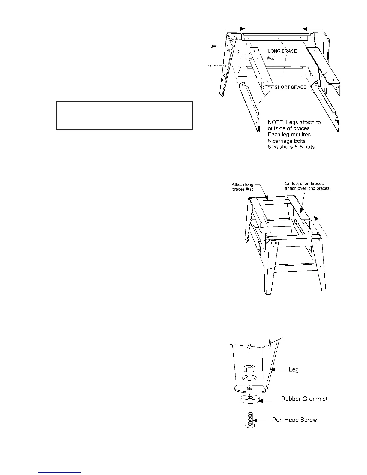
1. Assemble two leg sets using the long cross
braces attached to the inside of the legs. The lower
cross braces go into first set of square holes located
approximately center of each leg. See Figure 1. The
bottom holes on the legs do not apply to this ma-
chine. Use (32) 5/16-18 x 5/8 carriage bolts, (32) 5/16
hex nuts, and (32) 5/16 flat washers to assemble the
stand.
2. Attach the four short braces to one set of legs as
shown in Figure 2.
3. Complete the stand assembly by attaching the
other set of legs as shown in Figure 2.
4. To attach rubber feet to each leg, first use a
Phillips screwdriver and screw the 1/4-20 x 1 pan head
screw through the recessed hole of the rubber grom-
met as shown in figure 3. Push the screw through the
hole provided at the bottom of each leg, and tightly
fasten down with 1/4 flat washer and 1/4 nut.
5. Remember, leave all other stand assembly nuts
only finger tight!
FIGURE 1
FIGURE 2
FIGURE 3