20
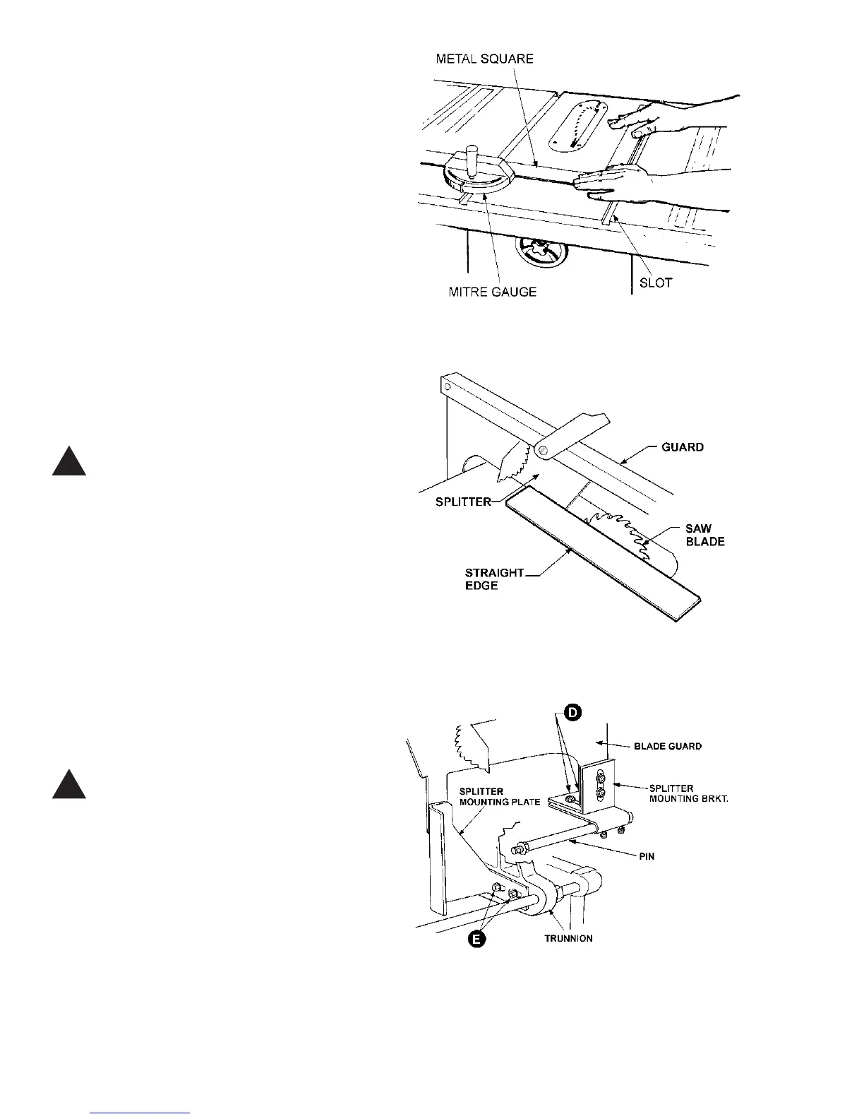
TO CHECK AND ADJUST THE 90 DEGREE SETTING
OF THE MITRE GAUGE, DO THE FOLLOWING:
1. Set the gauge at 90 degrees as shown in Figure
28.
2. Place a metal square against the face of the mi-
tre gauge and along one edge of the miter gauge slot
and check to see if edge of square fits flush with the
mitre gauge. See Figure 29.
3. If it does not, loosen lock handle (B - Figure 28).
2. Loosen locknut (E), and adjust the stop screw,
(A), so it strikes the stop link (D) when the gauge is at
90 degrees.
3. Retighten both the locknut (E) and lock handle
(B).
ALIGNING SPLITTER TO BLADE
CAUTION: The splitter assembly must be
aligned with the saw blade to help
prevent kickback.
1. Lay a straight edge against the saw blade and
the splitter as shown in Figure 30.
2. If splitter and blade do not line up, loosen the
lower screws on the splitter mounting bracket (D) and
the lower screws on the inside splitter mounting plate
(E) as shown in Figure 31.
(NOTE: This adjustment is more easily performed with
the aid of a helper since the mounting plate screws
are adjusted from the underside of the saw. A socket
wrench with extension may be necessary to loosen
the two screws).
3. When adjustment is finished, tighten all screws.
CAUTION: Make sure the blade guard and
splitter are parallel with the table mitre
slots to prevent binding.
ALIGNING BLADE TO T-SLOT
1. If the blade is not aligned with the slot in the
table, loosen the screws on the trunnion brackets (#17
and #54 - see page 35) and bump the table as needed
with a mallet.
2. Re-tighten screws securely when finished.
FIGURE 29
!
!
FIGURE 30
FIGURE 31