INDEX
23
K6 K8 K10 K20 | SERVICE MANUAL
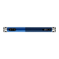
Remove the 7 screws that hold in place the amplier output board with a Phillips PH1 screwdriver, please be aware that on K20s screws
4 and 5 can be masked by the silicon glue.
Overview
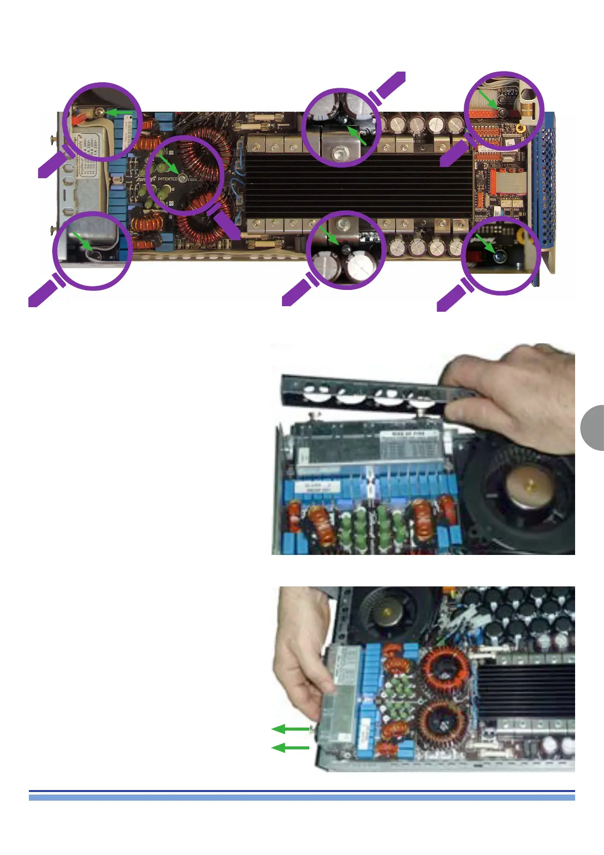
The amplier output board is now separated from the
amplier chassis.
Pull the rear panel back (Fig. 25) and move the board
back in order to disconnect the at cables located in
front of the board.
(Fig. 25)
It is now nally possible to remove the amplier output
board from the amplier chassis as illustrated in (Fig. 26)
(Fig. 26)