INDEX
31
K6 K8 K10 K20 | SERVICE MANUAL
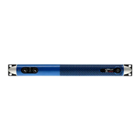
Remove the existing CTRL BOARD from the output stage
board and insert the SERVICE CTRL BOARD. (Fig. 46)
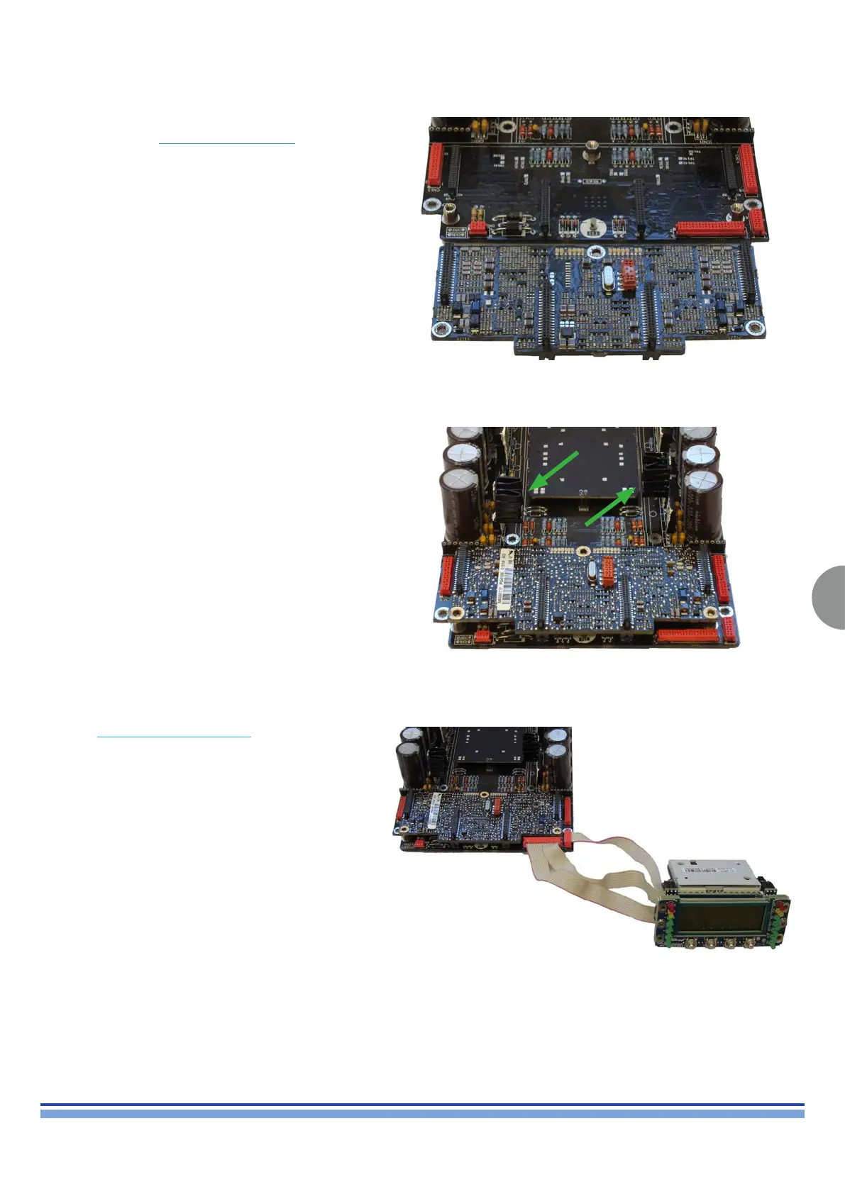
Install the two heat sink on the each voltage regulator U1,
U2 as portrayed in (Fig. 47)
Insert the SERVICE FRONT DISPLAY
Connect the ribbon cable (8 pins) to CN15
Connect the ribbon cable (20 pins) to CN16
(Fig. 48)
13. DC voltage test:
(Fig. 46)
(Fig. 47)
(Fig. 48)