INDEX
54
K6 K8 K10 K20 | SERVICE MANUAL
Prior to installing of the KAESOP board check if the rails are
completely discharged: leds in (Fig. 63) should be off, this should
happen 15 minutes after that the amplier has been switched off
and disconnected from the mains.
7railledsshouldbeofforit
isneededtodischarge
capacitorsbank
(Fig. 63)
(Fig. 64)
(Fig. 66)
(Fig. 67)
(Fig. 68)
(Fig. 65)
KAESOP board installation
It is possible to retrot the optional KAESOP board on every K
Series amplier with serial number greater than 19062, older
serial numbers need to be sent to Powersoft, please contact
Powersoft for further informations.
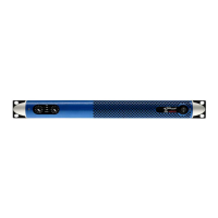
Powersoft KAESOP upgrade kit
Powersoft KAESOP upgrade Kit comes as two brass spacers,
two spacers, two at cables, a KAESOP board protected in an
electrostatic shielding envelope, a front panel RJ45 board pro-
tected in another electrostatic shielding envelope.
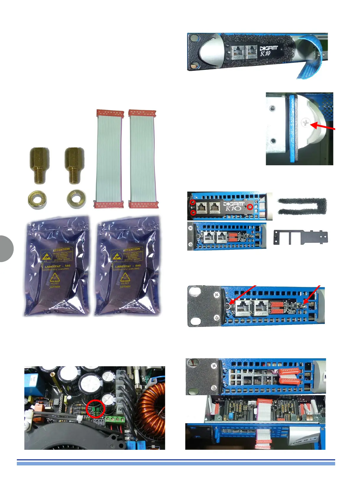
Open the front panel left grid removing the screw as in (Fig. 64).
Remove the screw to detach the
front panel left “ear” as in (Fig. 65)
14Blackmetalcoverandscrewstoremove,dustfilterandcoveronceremoved
The next step is to remove the dust lter and the the black metal
cover in front of the RJ45 board as showed in (Fig. 66)
15Blackmetalcoverremoved
Remove the original RJ45 circuit by unscrewing the black screw
and the brass spacer, keep them as you will need them for the
new circuit. (Fig. 67)
18Blackmetalcoverremoved
Once the original RJ45 board has been removed t the two at
cables as in (Fig. 68)
22Flatcableinserted,topview