INDEX
55
K6 K8 K10 K20 | SERVICE MANUAL
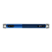
Once the at cables are inserted, position the new RJ45 board
using the same black screw and brass spacer support standoff
that were keeping the original RJ45 board in place, just set the
two spacers between the RJ45 board and the front panel (Fig. 69).
23RJ45boardwithscrewandspacersinposition
Then x the panel (Fig. 70)
24RJ45boardinposition
Secure the at cables to the two red plugs as in (Fig. 71), slightly
bending the top one in order to facilitate the repositioning of the
cover afterwards.
25flatcablesfittedonRJ45circuit
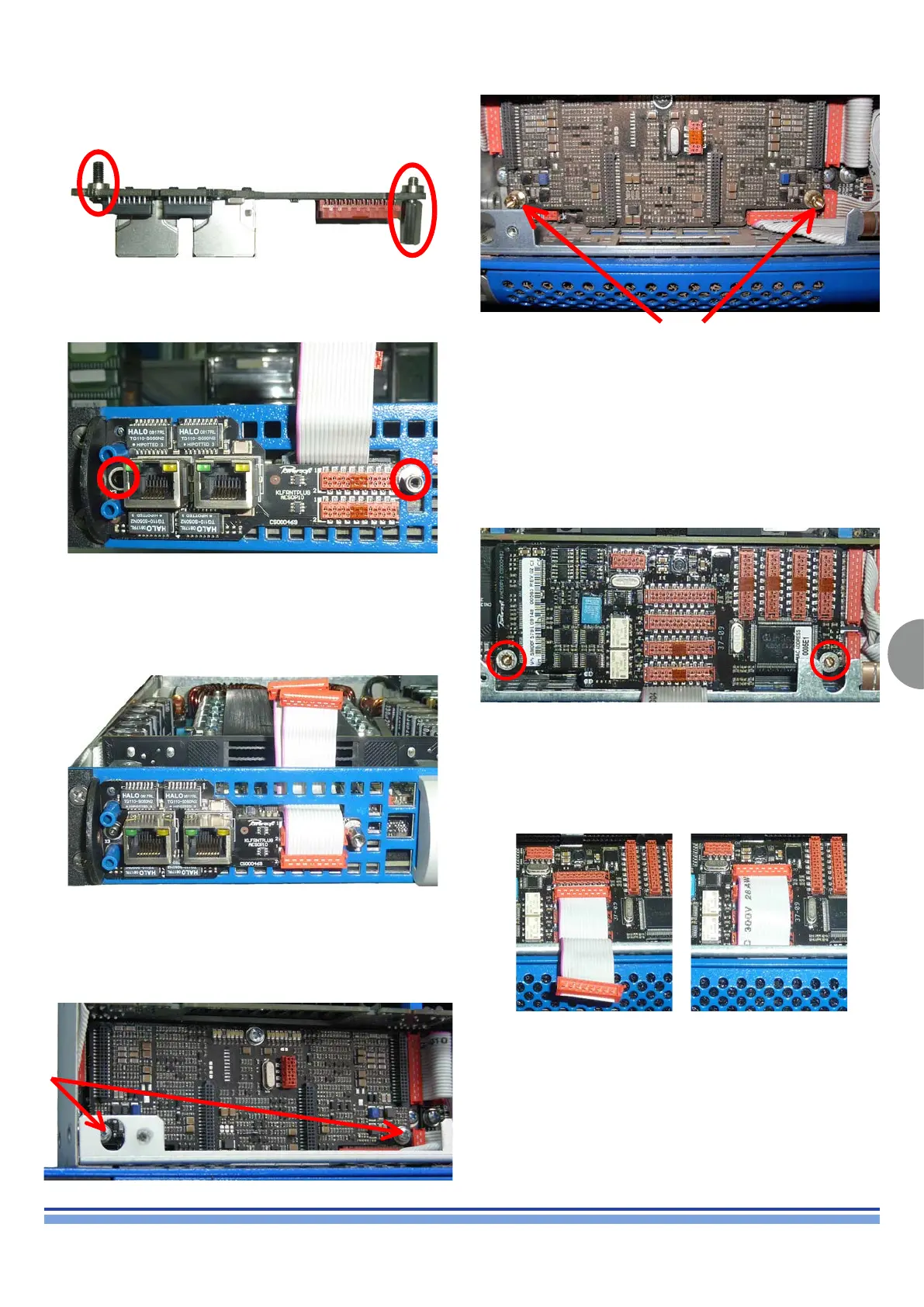
Locate the control board (or the DSP board if installed),
positioned in the front left corner of the amplier (Fig. 72)
and remove the screws with a Phillips PH0 screwdriver.
Once the KAESOP board has been correctly positioned on top of the
control board, pay particular attention to the four connectors of both
boards, they have to mate perfectly, do not press the board unless
you’re sure that the connectors are exactly in position. (Fig. 74)
Plug the KAESOP board on the control board (or K-DSP) and secure
it back on the two brass spacers, using the previously removed
screw. Do not over tighten them or you could damage the amplier.
29KAESOPboardcorrectlypositioned
Connect the two at cables: the lower one should be plugged in the
second horizontal red plug from the top of the board the top one should
be connected to the top connector on the KAESOP Board. (Fig. 75)
30Firstflatcablewired
31Bothflatcableswired
Reassemble the amplier’s cover.
(Fig. 69)
(Fig. 73)
(Fig. 74)
(Fig. 75)
(Fig. 70)
(Fig. 71)
(Fig. 72)
Screw the brass spacers provided with the KAESOP kit. (Fig. 73)