INDEX
24
K6 K8 K10 K20 | SERVICE MANUAL
Once the power supply board has been removed from
the amplier chassis as described in chapter 3, it is
possible to proceed in removing its single parts in order
to gain access to the component level repairs.
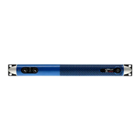
The rst step is to remove the heat sink.
Start by taking off the screws holding the springs that
keep the MOSFET pressed against the heat sink as
portrayed in (Fig. 27)
It is now possible to remove the plastic used as separator
between the MOSFETs and the capacitors (please note:
this may not be present). Distance the MOSFET from the
heat sink as illustrated in (Fig. 26).
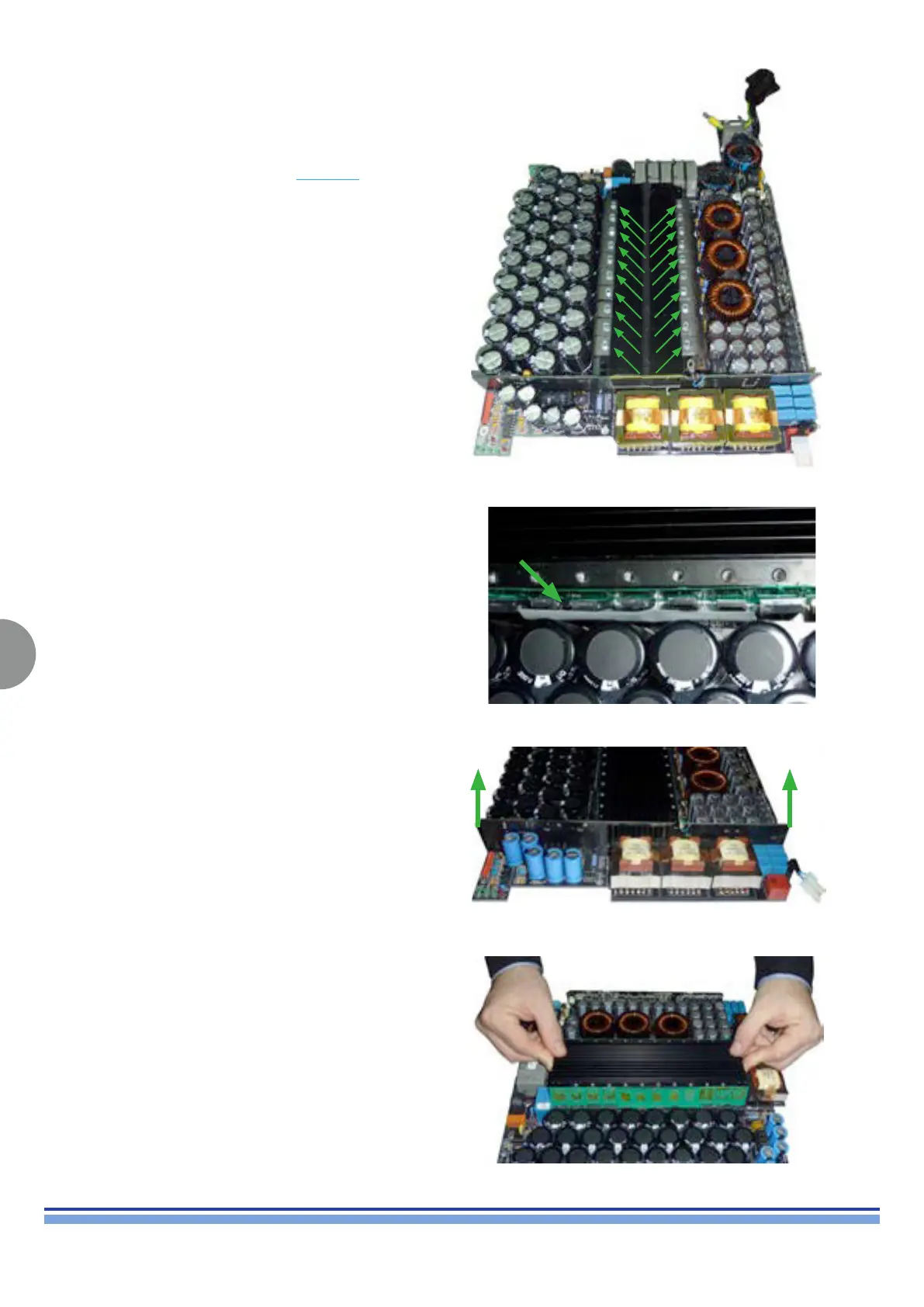
Remove the printed board in front of the heat sink by
pulling it up. (Fig. 27)
The heat sink is now free and can be lifted up and
removed from the power supply board. (Fig. 28)
8. Removing the KALIN Heatsink:
(Fig. 27)
(Fig. 28)
(Fig. 29)
(Fig. 30)