INDEX
32
K6 K8 K10 K20 | SERVICE MANUAL
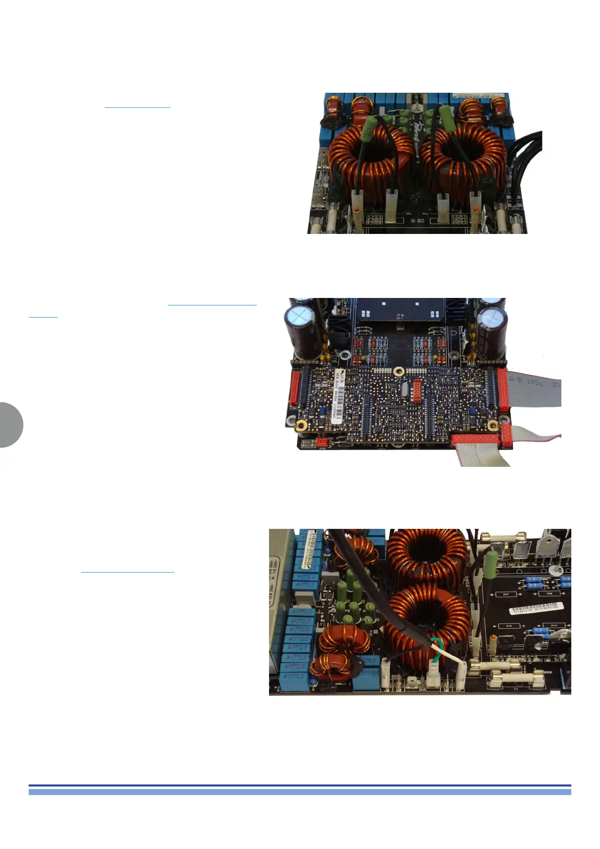
Connect the two Zobel Resistors on the male faston
connectors assembled on the output stage
FA13, FA14 for channel 1
FA15, FA16 for channel 2
(Fig. 49)
(Fig. 49)
Connect the ribbon cable (20 pins) K AMP VOLTAGE AUX
CABLE between CN14 of output stage board and the
power supply as shown in (Fig. 50)
Connect the RAIL BUS AUX CABLE on the output stage
board following the polarity of every single wire:
White wire FA7 (+VDC)
Green wire FA1 (GND)
Black wire FA9 (-VDC)
(Fig. 50)
(Fig. 51)
(Fig. 50)