INDEX
9
K6 K8 K10 K20 | SERVICE MANUAL
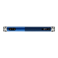
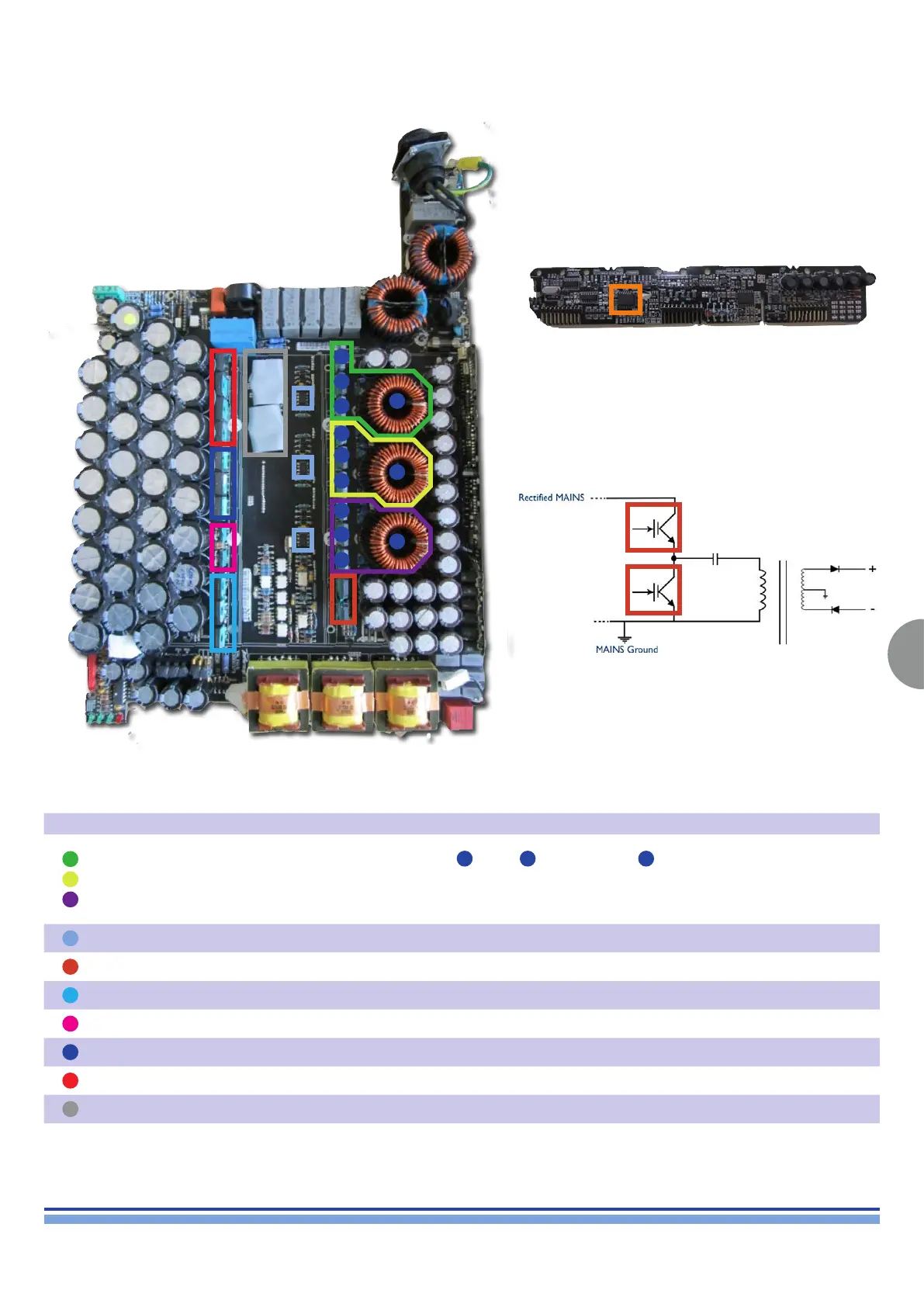
PFC Control Circuit
Same place of D & Q Series - PAY ATTENTION: It is a
different board!
Colour Description Notes
3 PARALLEL PFC BOOSTERS
Boosts the Output of P.F.C. to 410 VDC
COMPONENTS:
A
1 Coil -
B
2 Parallel IGBTs -
C
1 Diode
They work as a unique bigger P.F.C. Booster
Connected to the same P.F.C. Control Circuit
In case of fault check all components, and the PFC Control Circuit U3854
3 PFC DRIVERS Replace if the IGBTs of the P.F.C. are found to be broken!
2 IGBT Used for the DC/DC Converter
3 DIODES Secondary Rectier
2 TRANSISTORS Activate the Fans Independently
3 RESISTORS Sense current for the PFC
4 DIODES Bridge
2 NTC Limit inrush current
A
A
A
B
B
B
B
B
B
C
C
C
DC/DC Converter
P.F.C. Boosters