8 9
Electromagnetic Compatibility (EMC) & Safety
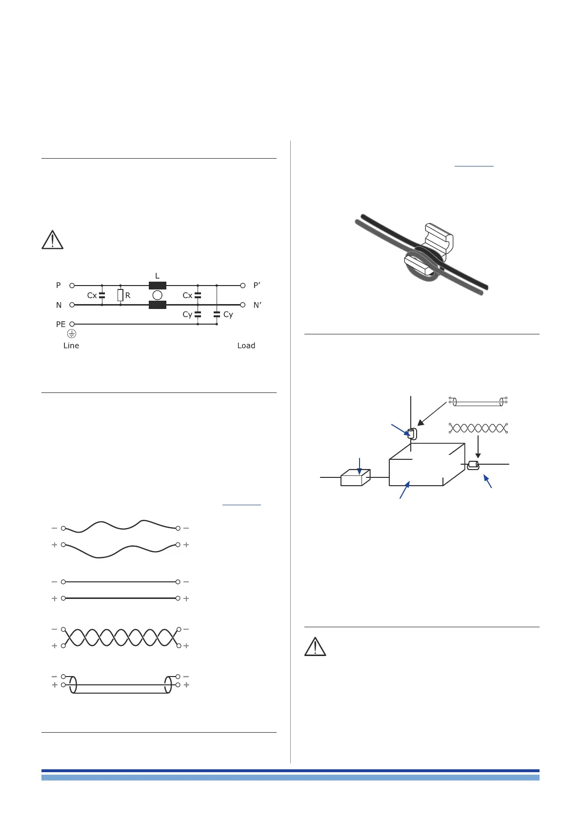
9 : 1.AC MAINS filter
This equipment has been tested and found to be compliant
with regulations listed in “Reference Standard” section.
This equipment is compliant with Class A of CISPR 32. In
a residential environment this equipment may cause radio
interference.
In order to improve the electromagnetic compatibility
an EMC lter must be inserted before the AC MAINS
plugs on the power supply. Powersoft suggests:
9 : 2.Cabling
Wiring between the amp module and the load may lead
to radio frequency noise. The following guide lines should
be observed:
f reduced cabling length is advisable;
f keep cable pairs as close as possible to each other in
order to minimize the antenna effect;
f design the cabling path far from RF noise source;
f set the cabling for RF noise rejection: shielded or twist-
ed cables are advisable conguration (ref. FIGURE 4);
f place ferrites as close to the module as possible
9 : 3.Ferrite cores
Reject RF noise from input and output cabling by in-
stalling ferrite shields. Powersoft suggests the FAIR RITE
0431164181, or equivalent.
Wrap both cables around one side of each ferrite so that
it pass through each ferrite twice (ref. FIGURE 3). Install the
ferrite shield as close as possible to where the cable plugs
into the amplier. Placing the ferrite elsewhere on the cable
noticeably reduces its effectiveness.
9 : 4.Chassis shielding
If not already present on the product, a full body metal
chassis or a shielding cage will provide best shielding of RF
emission. In order to achieve the highest shielding, minimize
the amount and size of holes or opening in the chassis.
FIGURE 2: Typical electrical schematic of the EMI Filter.
FIGURE 3: Ferrite core installation on I/O wirings.
Loose pair
Configuration
prone to high
RF noise
Parallel pair
Configuration
prone to RF noise
Twisted pair
Highly immune
to RF noise
Shielded pair
Highly immune
to RF noise
FIGURE 4: Cabling configuration.
Input
signal
FIGURE 5: Tools and best practice for improving
the electromagnetic compatibility.
AC MAINS filter
Chassis shielding
Amp module
inside
Ferrite core
Ferrite core
Output signal
9 : 5.Earth connection
This device must be powered exclusively by earth
connected mains sockets in electrical networks
compliant to the IEC 364 or similar rules. Is absolutely nec-
essary to verify this fundamental requirement of safety and,
in case of doubt, require an accurate check by a qualied
personal.
Is absolutely necessary to ground this device using the
proper earth connection on the metal frame of the chas-
sis; use M4 nut and bolt with proper split washer – grover
washer – to secure the earth terminal lug.
Electromagnetic Compatibility (EMC) & Safety | 3