Fault protections are systems designed to protect
people from severe or fatal electric shocks and avoid severe
damages on the amplier or the loudspeakers in case of
electrical parameters out of scaling or critical changes in
environmental conditions.
The architecture of Powersoft’s ampliers includes
several protection mechanisms triggered by harmful
signal and temperature. Protection systems and triggers
are independently implemented in the power supply
section (power supply protection) and the amplier section
(amplier protections) in order to minimize system damages
and maximize efciency.
In case any limiter requires >17dB of gain reduction,
each channel’s relative PROTECT pin (PL1000 - #10=ch1
#25=ch2, PL3000 - #10=ch3 #25=ch4) will become active.
If any limiter requires a >20 dB reduction, the module
will shut off.
13 : 1.Fan Control
Fan starts to run as soon as the amp module measures
a temperature greater than 60°, the fan control keeps fan
at maximum speed for the rst 2s, then its speed will be
controlled according to operating temperature. When the
amp module reaches 75°, the fan starts to run at maximum
speed.
The fan is not included in the package, Powersoft rec-
ommends the following (or equivalent):
f 80x80= SUNON, series ME80151Vx
13
Protections
13 : 2.1. Primary AC mains overcurrent protection
A surface mount 16A time-delay fuse prevents against
dengerous mains overcurrents in case of a internal failure.
The fuse is soldered on the PCB, it can be replaced only
by an authorized Powersoft Service Center.
13 : 2.2 . Primary AC mains overvoltage protection
LiteMod 4HV has a 400 VAC temporary tolerant power
supply. AC mains overvoltage threshold is set to about 280
V
RMS
. If the AC mains voltage exceeds 280 V
RMS
the primary
power supply stops working, but the auxiliary voltages
remain active.
The power supply turns on again when the AC mains
voltage drops under about 275 V
RMS
.
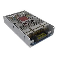
13 : 2.3. Primary thermal protection
The temperature is detected at the power supply’s
MOSFETs located on the Main Board’s bottom side and
inside the power transformer.
The limiting factor is set as follows: 0dB @ 105°C, and
-20dB @ 125°C. When the temperature exceeds the safety
threshold of 125°C, the system switches off.
T (°C) TempMon
25 2.95
30 2.87
35 2.78
40 2.67
45 2.53
50 2.37
55 2.19
60* 2
65 1.79
70 1.57
75** 1.31
80 1.05
85 0.76
90 0.47
*fan activation threshold
**max speed
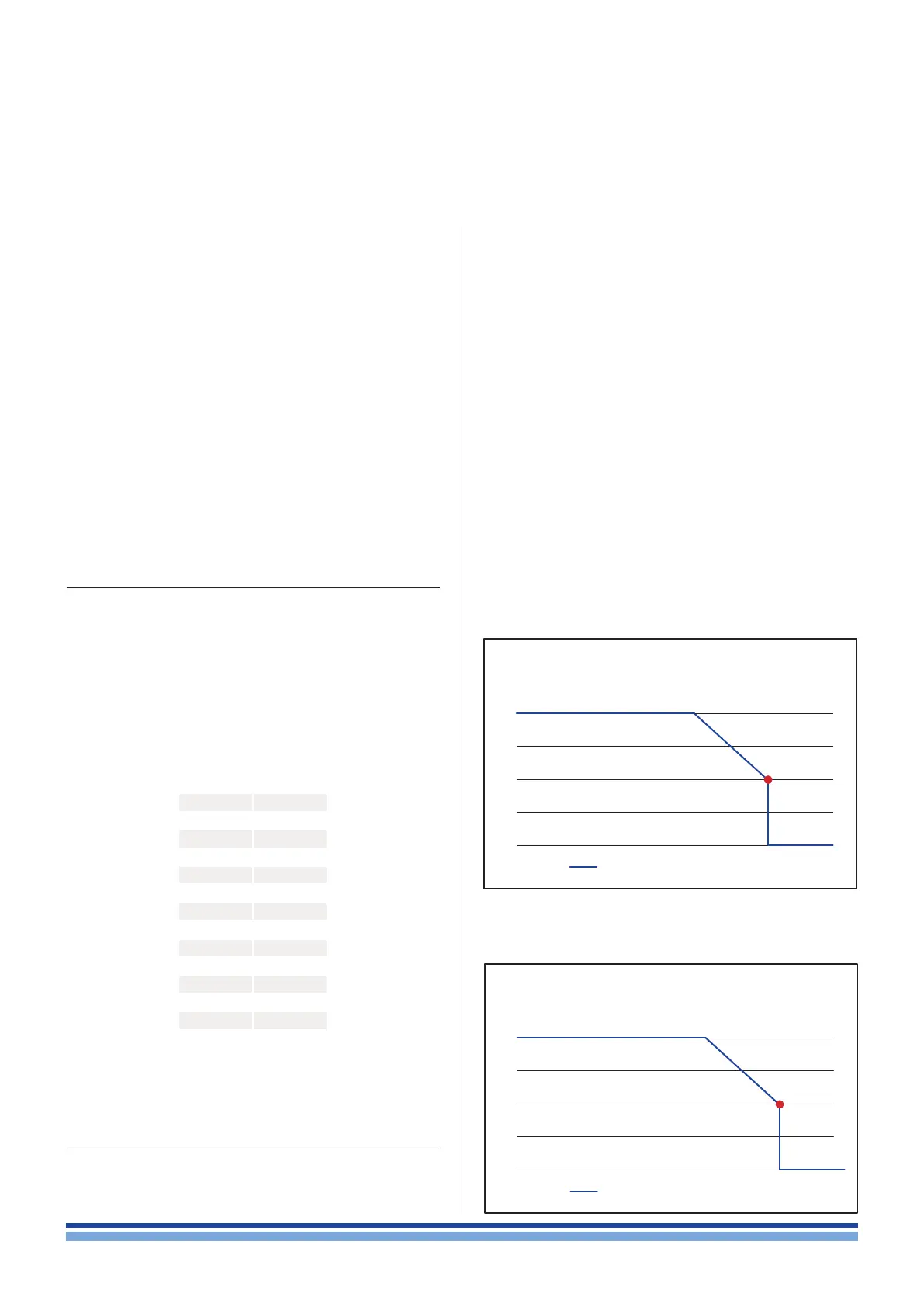
Another sensor is located on the heatsink, when the
temperature exceed the safety threshold (0 dB @70 ºC, -20
dB @85º C), the system switch off.
TABLE 1: TempMon
13 : 2.Power supply protections
Power supply protections aim to avoid damages due to
stress of the Power supply or to isolate a faulty section in the
electrical power system from the rest of the device in order
to prevent the propagation of the fault and limit damages.
Protections | 14
0
-10
-20
80 95 125
-30
o
C
dB
-∞
Gain Reduction
Safety
Shutdown
Transformer
temperature limiter
115
0
-10
-20
0 65 70 85
-30
o
C
dB
-∞
Gain Reduction
Safety
Shutdown
Heat-Sink
temperature limiter