10 | LiteMod 4HV | User guide
GND
Parallel
-
+
-
+
GND
Parallel
+
-
+
-
CH1
CH3
CH2
CH4
Parallel
Parallel
4 x 750 W @ 4 Ω
GND
Parallel
-
+
-
+
GND
Parallel
+
-
+
-
CH1
CH3
CH2
CH4
Parallel
Parallel
2 x 1400 W @ 8 Ω BTL
GND
Parallel
-
+
-
+
GND
Parallel
+
-
+
-
CH1
CH3
CH2
CH4
Parallel
Parallel
2 x 750 W @ 4 Ω
1 x 1400 W @ 8 Ω BTL
GND
Parallel
-
+
-
+
GND
Parallel
+
-
+
-
CH1
CH3
CH2
CH4
Parallel
Parallel
2 x 1400 W @ 2 Ω PTL
GND
Parallel
-
+
-
+
GND
Parallel
+
-
+
-
CH1
CH3
CH2
CH4
Parallel
Parallel
1 x 2400 W @ 4 Ω PBTL
GND
Parallel
-
+
-
+
GND
Parallel
+
-
+
-
CH1
CH3
CH2
CH4
Parallel
Parallel
4 x 750 W @ 4 Ω
GND
Parallel
-
+
-
+
GND
Parallel
+
-
+
-
CH1
CH3
CH2
CH4
Parallel
Parallel
2 x 1400 W @ 8 Ω BTL
GND
Parallel
-
+
-
+
GND
Parallel
+
-
+
-
CH1
CH3
CH2
CH4
Parallel
Parallel
2 x 750 W @ 4 Ω
1 x 1400 W @ 8 Ω BTL
GND
Parallel
-
+
-
+
GND
Parallel
+
-
+
-
CH1
CH3
CH2
CH4
Parallel
Parallel
2 x 1400 W @ 2 Ω PTL
GND
Parallel
-
+
-
+
GND
Parallel
+
-
+
-
CH1
CH3
CH2
CH4
Parallel
Parallel
1 x 2400 W @ 4 Ω PBTL
f 2 x BTL - 2 x 2000 W @ 8 Ω
GND
Parallel
-
+
-
+
GND
Parallel
+
-
+
-
CH1
CH3
CH2
CH4
Parallel
Parallel
4 x 750 W @ 4 Ω
GND
Parallel
-
+
-
+
GND
Parallel
+
-
+
-
CH1
CH3
CH2
CH4
Parallel
Parallel
2 x 1400 W @ 8 Ω BTL
GND
Parallel
-
+
-
+
GND
Parallel
+
-
+
-
CH1
CH3
CH2
CH4
Parallel
Parallel
2 x 750 W @ 4 Ω
1 x 1400 W @ 8 Ω BTL
GND
Parallel
-
+
-
+
GND
Parallel
+
-
+
-
CH1
CH3
CH2
CH4
Parallel
Parallel
2 x 1400 W @ 2 Ω PTL
GND
Parallel
-
+
-
+
GND
Parallel
+
-
+
-
CH1
CH3
CH2
CH4
Parallel
Parallel
1 x 2400 W @ 4 Ω PBTL
f 4 x SE - 4 x 1000 W @ 4 Ω
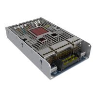
11 : 4.Internal Signal Path Polarity
In order to increase the power’s supply energy stor-
age efciency, signals coming from channel pairs 1-2 are
reversed in polarity.
This ensures a symmetrical use of the voltage rails: if,
for example, both channels 1 and 2 input signals are go-
ing through a peak at the same time, channel 1’s energy
will come from the positive voltage rails while channel 2,
whose polarity is reversed with respect to channel 1, will be
fed energy from the negative voltage rails. In this manner,
the power supply will work symmetrically, with one channel
driven by the positive rails and the other by the symmetrical
negative rails. Channel 2’s signal will be polarity reversed
once more to ensure that both channels output with the
same polarity as their corresponding input signals.
For this reason it is very important not to invert the po-
larity of either channels before feeding them to the module.
A double polarity inversion (the rst by the user inserting
the input signal and the other by the amplier’s internal
circuitry) results in no inversion at all. If this were the case,
both channels would be weighting on only one side (positive
or negative) of the power supply’s voltage rails. This would
result in an inefcient use of the power supply’s energy.
Please pay special attention in using balanced inputs on
all measurement equipment (such as oscilloscope probes)
when you are bench testing.
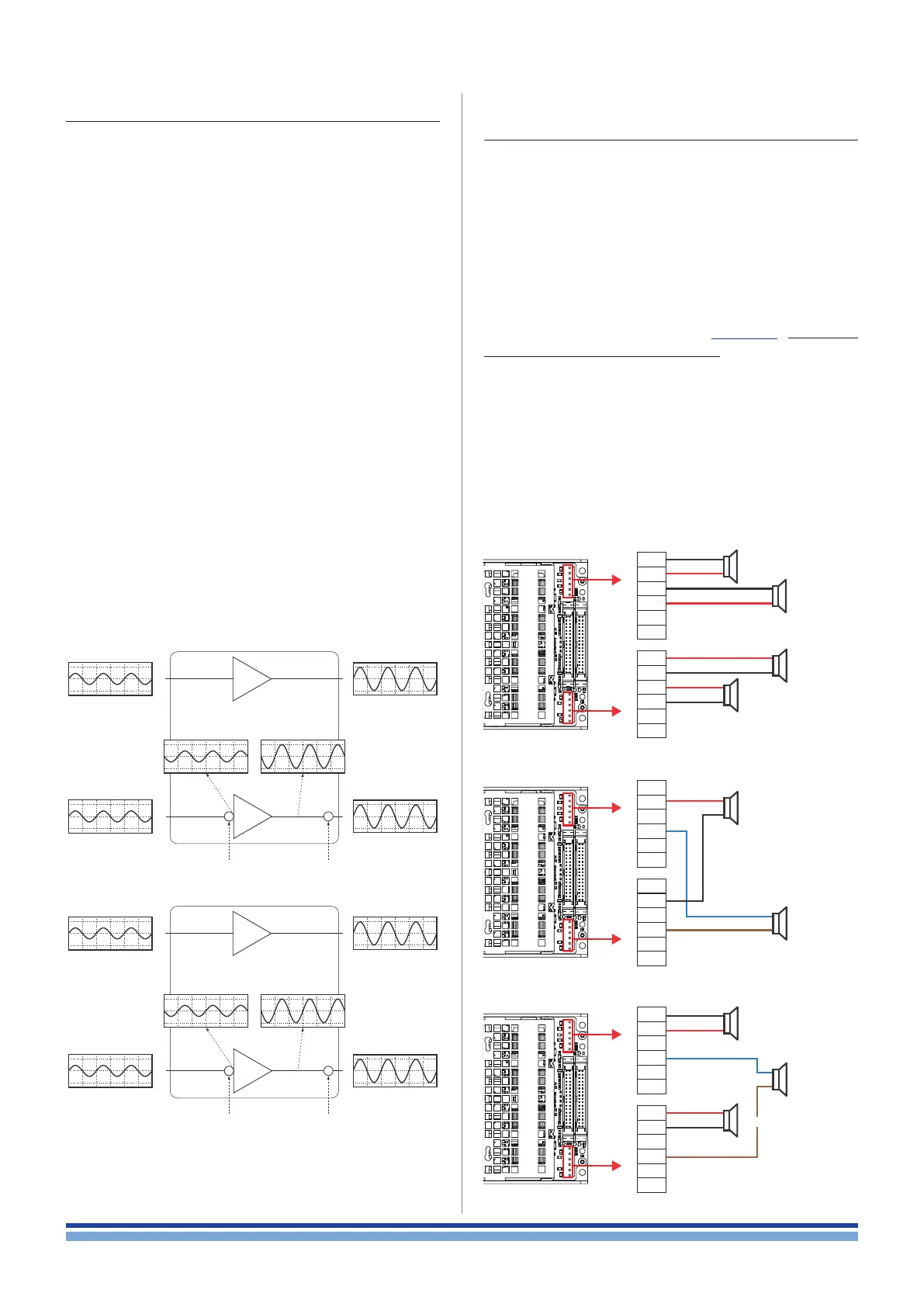
11 : 5.Output Configuration
LiteMod 4HV can be congured in 5 different output
type of connections:
4 x SE (Single Ended): 4 indipendent channels.
2 x BTL (Bridge Tied Load): Two couples of channels
bridged.
2 x SE + 1 x BTL: A couple of channel bridged while the
remaining two channels kept single ended.
2 x PTL (Parallel Tied Load); Two couple of channels
obtained by paralleling two channels of the module. This
conguration can be activated by short circuiting two pins
of output connector indicated on FIGURE 8, it must be
done before switching on the module. Activating the parallel
mode on one of the output connectors, implies setting up
parallel mode on both channel pairs. For safety reasons we
suggest to apply the parallel mode on both connectors.
1 x PBTL (Parallel Bridge Tied Load): A single channel
can be obtaned by bridging the PTL conguration.
When setting up the PTL mode, input signals must be
applied only on PL1000 connector (only one ribbon cable
needed): input #1 will drive outputs CH1 and CH3 while
input #2 will drive outputs CH2 and CH4.
f 2 x SE + 1 x BTL - 2 x 1000 W @ 4 Ω + 1 x 2000 W @ 8 Ω
rst polarity
inversion
second polarity
inversion
Channel 1
input
Channel 2
input
Channel 1
output
Amp
Channel 2
output
1/2
3/4
rst polarity
inversion
second polarity
inversion
Channel 1
input
Channel 2
input
Channel 1
output
Amp
Channel 2
output
1/2
3/4
FIGURE 7: Internal signal path polarity with example input
signals. All channels are fed with the same sine signal.
1
OUT 1
OUT 3
OUT 2
OUT 4
OUT 1+2
OUT 3+4
OUT 1
OUT 2
OUT 3+4
3
3
4
3
4
2
4