22
Powerware 9315 (100 kVA--160 kVA) Installation
164200292 REV. E 041500
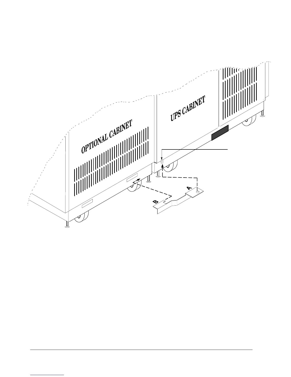
9. Hold the angled bracket parallel to the floor (see Figure 10). The flange with
theholeinit(labeledA in Figure 10) should be facing upward. The flange with
the tab (labeled B in Figure 10) should be pointing toward the slot in the base
of the optional cabinet.
Lower
door hinge
Figure 10. Installing the Angled Bracket
10. Insert the tab (B) into the slot in the base of the optional cabinet.
11. SlidethebrackettowardtheUPScabinetwhileslippingthehole(A) onto the
screw in the lower door hinge of the UPS cabinet.
12. Install the nut (removed in step 8) on the hinge screw to secure the angled
bracket in place.
13. Repeat steps 2 through 12 to join another optional cabinet to the other side of
the UPS cabinet.
14. Attach a ground wire to the joined cabinets using the procedure “Grounding
Joined Cabinets” in this chapter.



 To Next Page